
Comprehensive comparative studies of various anodic oxide microstructures and their corresponding engineering properties enabled new scientific insight for the mechanism of anodic oxide formation on aluminum and aluminum alloys.
 Dr. Runge and Aaron PomisThe understanding of structure-chemistry relationships during anodic oxide formation led to the development of a new anodic oxide finish, a polymer-metal oxide composite, that exhibits engineering properties superior to conventional anodic oxides: Type I (Chromic Acid), Type II (conventional “clear coat”) and Type III (Hard Anodized) when processed to equivalent practical thicknesses and compared in similar test applications.
The results indicate the importance of understanding the anodizing process and the synergy between process, microstructure and engineering properties to bring innovation and improvement to a mature industry.
Introduction
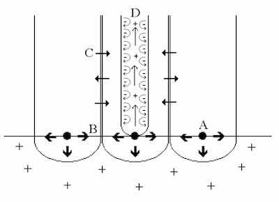 Figure 1: The Constraint Theory of Anodic Oxide Formation. A: Preferential nuclei form base of pore. B: Repulsive forces between similarly charged oxide “flakes” foster outward growth. C: Mass transport and diffusion across column walls form intercolumn “knit lines”. D: Repulsive forces within each pore maintain the erect nature of the column and dynamic flow of the electrolyte.Under typical atmospheric conditions, a native oxide or passive film naturally forms on aluminum. The native oxide layer is nonuniform, thin and noncoherent. Nevertheless, the native oxide film imparts a certain level of corrosion protection, provided the environment contains no unusual contaminants. Exfoliation, the formation of a network of oxide flakes or “leaves” on the aluminum surface, is an example of how corrosion of the surface can be changed through the introduction of sulfur to the environment. In fact, removing sulfur from the atmosphere can stop the exfoliation of aluminum oxide[1-3].
Anodizing aluminum is a sturdy fixture in the mind of the light metal industry. By capitalizing on the natural phenomenon of passive film formation on aluminum in a production environment, the anodization process has become synonymous with surface protection and durability of aluminum substrates. Anodizing can be viewed as the deliberate, controlled corrosion of the aluminum surface in sulfuric acid to yield a uniform, continuous protective oxide film. Its uniquely self assembling, highly ordered, columnar nanoscale structure has been extensively studied, yet the mechanism of anodic oxidation of aluminum is still not fully established. This paper discusses a mechanism for film formation based in the results of our comprehensive microstructural and chemical studies of conventional and modified Type I (Chromic Acid), Type II (conventional “clear coat”) and Type III (hard anodized) anodic films.
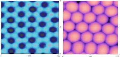 Figure 2: AFM images of anodized aluminum oxide finishes after careful removal from the aluminum substrate. (Left) surface of the aluminum substrate surface. Each dark spot is the nucleation point of the oxide during surface reconstruction. The lighter areas surrounding each nucleation point are the areas where the column walls intersected the substrate; the shaded spots are areas of impingement and deformation where the knit lines intersected the substrate. (Right) bottom surface of the anodized finish showing it as a distinct hexagonal network. Note the interstitial spaces between the network columns.The results of these studies show that anodic finishes exhibit a microstructural and compositional gradient. Through scientific characterization of the various film features, and a clear understanding of the anodizing process parameters used to yield the various films, we developed a new formulation of a heavy metal free electrolyte utilizing an electroactive polymer additive to a sulfuric acid based electrolyte. Studies comparing the resultant composite anodic oxide to conventional Type I, II and III anodic finishes have determined the composite anodic oxide exhibits superior corrosion and abrasion resistance as well as the ability to function as a dual-phase transition layer for polymer-metal bonding [4-5]. Comparative mechanical testing by way of fatigue, friction and thread torque tests determined the composite oxide meets or exceeds the mechanical performance of components finished with conventional methods, regardless of Type.
Development of a New Process
Through the course of our work which was undertaken at the University of Illinois at Chicago, Saporito Finishing in Cicero, Illinois, and Bodycote Nussbaum in Kaufbeuren, Germany, to understand the mechanism of anodic oxide formation, we developed a new theory for porous oxide formation which challenges the convention that dissolution is the dominant mechanism for the porous oxide structure. Another result of this work was the development of a new anodic oxide finish that is described later in this paper.
Process and Microstructure
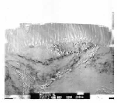 Figure 3: X15,000 Documentary TEM photomicrograph of an anodized aluminum substrate. Note the presence of circular inclusions (iron-chromium) which had been taken up into the Type III columnar structure during anodization. Atomic level defects in the aluminum substrate are seen to affect the finish structure at the finish-substrate interface.Extensive Transmission Electron Microscopy (TEM) was performed on a variety of anodized finishes, processed in various ways. Ultramicrotome sections of conventionally processed and unsealed Type I, Type II and Type III anodized films were further prepared for Transmission Electron Microscopy (TEM) by way of Precision Ion Processing (PIPs). The films were imaged and analyzed by way of TEM with Electron Energy Loss Spectroscopy (EELS).
Analysis results consistently show that process modifications, whether chemical (to the electrolyte) or electrical (to the electrical input) impart distinct microstructural changes to the anodic oxide compared with the microstructures of anodic oxides formed through conventional processing.
By virtue of these changes and the predictable manner in which they can be achieved, we proposed The Constraint Concept of Film Formation. This theory explains how various oxide microstructural characteristics are achieved through electric field effects, and through diffusion and mass transport that occur within the anodic oxide during anodizing, and how they change through modifications to the process [6].
A summary of our theory follows:
The kinetics of anodic oxide film formation are governed by (1) the thermodynamics at the surface and (2) diffusion and mass transfer across the oxide layer as it forms [7]. Surface reconstruction, the result of chemisorption, which precedes surface oxidation, begins at preferred nucleation sites on the substrate surface [8]. The thermodynamics of the surface favor only aluminum oxidation, therefore alloy additions and other contaminants can retard the reaction kinetics.
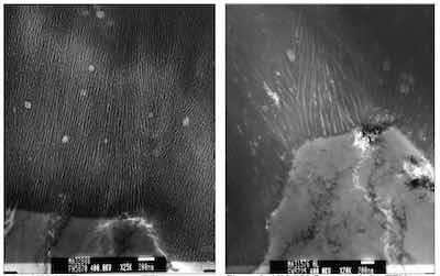 Figure 4: X25,000Representative TEM photomicrograph of a Type II anodized finish. Figure 5: X20,000 Representative TEM photomicrograph of a Type III anodized finish.Our research and analysis conclude the columnar structure of the anodic film is the result of lateral film growth following surface reconstruction during early stages of the oxide growth process, rather than selective dissolution of the oxide as reported in the past [9], [10]. As the “infant oxide” flakes impinge on one another, the repulsive forces of the similarly charged oxide flakes foster outward growth of the finish. Pores in the oxide finish are formed through repulsive field effects on the “inside” surface of the flakes, as the oxide flakes impinge and grow outward. It is apparent that mass transport of the forming hydrated aluminum oxide network across the column outer walls knits the structure together. The stability and robustness of the final structure appear to depend on this stage of the film formation because there is no ion flow that can disturb diffusion or mass transport across these interfaces, between each forming column, as in the pores. Consequently, the mechanical and chemical integrity of the finished film often is based on the integrity of the knitlines. See Figures 1 and 2.
Since the thermodynamics at the substrate surface favor the formation of aluminum oxide, aluminum is the only element besides oxygen reacting to form the finish. This means that other alloying elements are entrained at the substrate interface. Other atomic level defects, such as dislocations and vacancies are also “left behind”. In fact, these defects at the interface are transported with the oxide flakes during lateral growth of the finish. Concentrations of these defects can be seen interstitially, between oxide column bases. Inclusions, inert to the anodization process and incoherent with the base metal microstructure, can also be transported into the finish as it grows; moving with flakes as they grow outward from the substrate surface. See Figure 3.
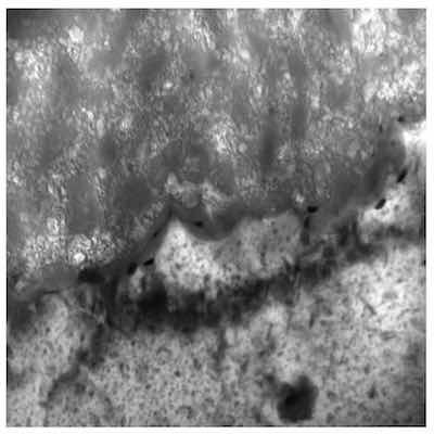 Figure 6: X100,000 Representative photomicrograph of a Type I microstructure at the aluminum – anodic oxide finish interface.Pore wall reactivity enables adsorption of the electrolyte counter ions, additives, and seals. In situations where the additive is not electroactive, adsorption occurs after substrate consumption is complete; however, analysis has shown that electroactive counter ion adsorption occurs throughout anodic oxide formation.
Reactivity/passivity of the adsorbed counter ion dictates film thickness. An adsorbed reactive counter ion facilitates charge transfer along the inside surface of the oxide flake. The charge transfer fosters the oxidation reaction such that the repulsive forces of the ions promote pore formation and outward growth of the columnar microstructure. Therefore the process parameters utilized for a typical Type II anodic finish yield a nanostructure with more columns and finer column walls up to 20 – 25μm thick than a Type III process, in which the parameters yield a nanostructure with fewer columns and coarser (thicker) column walls up to 50μm thick. It is clear through this comparison that the lower process temperature (with Type III, for example) reduces the initial number of oxide nucleation points during surface reconstruction and that increased current density increases both the column thickness and pore diameter. See Figures 4 and 5.
An adsorbed passive counter-ion, such as a chromate ion in a Type I anodization process, will not facilitate charge transfer along the inside surface of the oxide flake and outward growth of the oxide layer does not occur, instead, would-be columns collapse on one another. Therefore, unlike conventionally processed Type II and Type III anodic finishes that exhibit a columnar nanostructure, the Type I nanostructure is coarse and disordered.
The Type I microstructure exhibits a dense, random microstructure with a heavy interfacial reaction layer. The finish is thin, on the order of 1.5 to 2μm. These features are the result of the high temperature, high current density process parameters in an electrolyte that contains passive metal ions. From an engineering perspective, the random microstructure imparts the corrosion resistance of the Type I finish; the process parameters as well as the passive nature of the chromate ion limit finish thickness which in turn preserves component tolerances and fatigue resistance. See Figure 6.
Chemical analysis via EELS and imaging by way of diffraction contrast show conclusively that the various common finish Types are comprised primarily of disordered hydrated aluminum oxide, i.e. aluminum hydroxide. The anodic finishes, regardless of Type, are amorphous and do not exhibit any diffraction contrast necessary to identify the oxide phase as corundum, α alumina, Al2O3. Furthermore, related research has disclosed the only crystalline anodic films are those formed by way of spark anodization, where the crystalline phase of alumina formed through the process was determined to be γ alumina [11].
Microstructure Modification
Based upon the ideas proposed in the Constraint Concept of Film Formation [6], in order to modify an anodic finish, change must be introduced that is electroactive or “charged” in nature. Therefore, one can change the external electrical parameters of the anodization process, or change the electrolyte through the introduction of a supplementary counter ion. The counter ion can be active or passive, or completely inert. Active counter ions will facilitate finish growth, as with an oxalate ion. Passive counter ions will react with the pore wall but oxidize immediately as with a chromate ion, limiting finish growth. An inert additive may be a surface active agent that although soluble in the electrolyte, does not participate in the anodization reaction at all. These additions serve, through esterification or similar reaction, to buffer the heat of reaction that occurs with alloy additions, interfacial defects and contamination and help prevent finish damage due to resistance heating.
We selected a novel active counter ion as an electrolyte modifier. Similarities between the aluminum anodization process and the oxidative polymerization reaction for certain conjugated polymers, as well as the electroactive characteristics of these polymers when doped with protonic acids, such as sulfuric acid, indicated anodizing and electrodeposition of the polymer could be carried out simultaneously, producing fully integrated composite polymer – metal oxide finishes. Therefore, electroactive polymer was added to the sulfuric acid electrolyte. Uniform, continuous composite aluminum oxide finishes have been electrochemically produced with this polymer- modified electrolyte which exhibit structural modification and polymer phase inclusion in both laboratory and production environments. It will be referred to from now on as the composite anodic oxide finish.
Scientific Characterization
Transmission Electron Microscopy
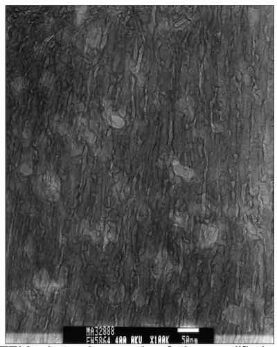 Figure 7: Representative TEM photomicrograph of the modified structure of a composite anodized film. Note the cellular, rather than directly columnar structure.TEM analysis of the composite anodic oxide finish produced in the modified electrolyte determined it exhibits a unique hybrid microstructure. Instead of long, straight columns as Type II or Type III anodic oxides, or a dense, random microstructure as a Type I anodic oxide, the composite finish exhibits a more cellular structure. The composite microstructure still has a columnar character but the columns are without a continuous, unidirectional central pore, especially near the finish surface when the process is controlled to yield thicknesses comparable to Type II or III anodic oxides; or throughout the thickness when the process is controlled to yield thicknesses typical of a Type I finish. These results indicate adsorbed electroactive polymer additive maintains pore wall surface reactivity enough to foster outward growth of the anodic oxide finish, but that most of the modification occurs in the first stages of the oxide formation. It also indicates the modifier, which has been determined to be an aluminum salt of the sulfonated conjugated polymer additive, actually participates in the ion pump within the pores during finish formation. See Figure 7.
High Intensity Infrared (FT-IR) Spectrographic Analysis
TEM sections of a Type II unsealed anodic film and a composite film were analyzed by way of high intensity micro-Fourier Transform Infrared Spectrographic analysis. The energy source for the instrument was hooked up to a synchrotron light source. The resolution of the instrument was 4 – 5μ. Sections of each coating were analyzed using a 4μ X 30μ aperture. Data was collected from the aluminum-anodic film interface (bottom), the film center and the top. The films measured 20-25μ thick.
The trends in the infrared data collected from the bottom of the films to the top strongly indicate a shift in the formation and amount of active hydroxide and sulfate groups. The Al-O feature at approximately 750 cm-1 dominates, but shifts upward in the spectra as the sulfate peaks at 1000 to 1100 cm-1 become larger and more defined. With the development of the sulfate absorption, hydroxide absorption becomes pronounced. This makes sense, as the surface of the anodic finish regardless of Type or formulation, should exhibit more hydration.
The composite finish exhibited evidence of inclusion of the electroactive modifier with absorption in the higher IR. The spectral shifts toward the higher IR were noted from the substrate, where the inorganic absorbances were most pronounced to the middle and finally the surface portions where absorption of both OH-1 and carbon-based inorganic salts were detected within the composite film. See figure nos. 9 and 10.
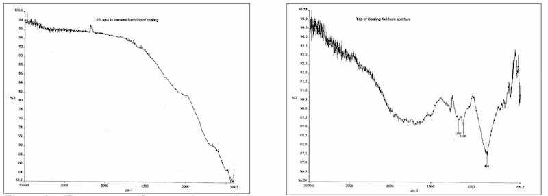 Figure 9: IR spectrum of composite anodic film adjacent to the aluminum substrate is identical to a conventionally anodized Type II film. The low end absorbance is typical for inorganic species.; Figure 10: IR spectrum of modified composite film exhibits a shift in the inorganic spectrum toward the more chemically reactive species of sulfate and hydroxide. Some organic absorbances are also present indicative of additive inclusion.
A hot water sealed Type III coating was processed within argon plasma. With increased exposure time within the plasma, a residue developed on the surface of the coating. Infrared analysis of the residue determined absorption characteristics for hydrated aluminum sulfate and/or aluminite: Al2(SO4) • 18H2O and/or Al2(SO4)(OH)4 • 7H2O.
These results indicate consideration should be given to the stability of the oxide phases from the column wall to the pore center as well as from the substrate interface to the film surface. The portions of the film that remain in contact with the electrolyte, in addition to hydration, will also adsorb active counter ion species from the electrolyte, forming a compositional and therefore reactivity gradient across the porous structure.
X-ray Photoelectron Spectroscopy
X-ray Photoelectron Spectroscopy (XPS) studies were performed on Type II and on two (2) groups of composite anodized samples. The composite samples were exposed to different anodizing times. One group of samples was representative of the typical exposure time of 60 minutes and the other group was representative of an extended exposure time. The samples were anodized and mechanically removed to sealed containers to prevent surface contamination through handling or by ambient air. This insured the analysis results would reflect the actual anodized surface composition from a depth of 0 to 30 Angstroms.
The Type II and composite samples anodized for the typical exposure time exhibited the presence of sulfur as sulfate. Additional oxygen and aluminum was also detected. The high-level binding energy component for oxygen corresponded to H2O and OH-, which were consistent with the infrared data. The aluminum detected in the film surface of these samples was not metallic in nature; the low binding energy component was typical for disordered aluminum oxide. The composite sample did show chemical inclusion of the electroactive modifier. Saturated and π - conjugated carbons were noted with distinct linkages to the disordered (hydr)oxide structure as HO-C=O, O-C=O and C-OH.
XPS analysis of the extended exposure samples determined strikingly different surface constituents. More of the electroactive additive was detected in the surface of these samples. No sulfur was determined. Evidence of metallic aluminum, aluminum as Al2O3, and copper, as Cu2O was also identified. The results were important because they indicated these species were actually deposited from the electrolyte and not a function of the anodization of the substrate.
Engineering Characterization
Intensive comparative engineering tests of several types of anodized aluminum finishes were performed with the composite anodic oxide finish. Testing was performed to determine and compare corrosion resistance, color fastness when dyed, smoothness, abrasion and wear resistance, coefficient of friction in comparable wear systems, fatigue testing and bonding of subsequent polymer layers [4], [5].
In most cases, significant improvements were noted in the performance of the composite anodic finish over its conventional counterparts when tested at equivalent thicknesses. When testing determined the composite finish performed comparably, added benefits were noted in the form of energy savings, as the oxide formation current density was lower and process temperature ambient for the composite finish. In addition, the electrolyte is heavy-metal free, easing waste treatment costs and concerns and avoiding pollution hazards typically associated with Type I (Chromic Acid) anodization processes [12].
Conclusion
By varying process parameters that impact the microstructure of the anodic oxide finish, the metal finishing industry has established three basic, yet distinct, types of anodic finishes for aluminum, each with different engineering properties and therefore applications. Numerous commercial chemical additives are currently available with corresponding engineering data which suggest the various types of anodic oxide finish can be enhanced, but no real scientific data is available to support their results.
In our research and development program, enhanced understanding regarding the mechanisms of anodic oxide finish formation and the process to control them determined further changes could be made to the anodization process that could result in a new type of finish with properties that exceed the limitations of conventional finish types. With these ideas in mind, a new type of anodic oxide finish, formed with a polymer-modified electrolyte, was invented.
Through comprehensive scientific characterization of the resultant composite anodic oxide finish, its structure and chemical constituents, a correlation to its superior engineering characteristics, important to the application and service life in various industries, could be drawn. To date, engineering testing of the composite finish has shown superior corrosion and wear resistance to conventional Type I, II and III finishes, as well as increased dye-ability, UV stability and superior adhesion of subsequent polymer layers. Testing has been performed in the laboratory and in various field applications that demonstrate the composite finish, at comparative Type I thicknesses, does not impact the fatigue strength of the substrate. The formulation is successfully implemented in large scale production.
By understanding the age-old process of anodizing aluminum, new, improved and truly different anodic finishes can be developed and brought to a market complacent with mature designs.
Jude M. Runge, Ph.D. is with CompCote International; Aaron J. Pomis is with the University of Illinois at Chicago.
References
- Uhlig, H.H., Corrosion and Corrosion Control, Wiley,NewYork,1985.
- Jones, D. A., Principles and Prevention of Corrosion, MacMillan Publishing Company, New York, 1992.
- ASM International Metals Handbook, Tenth Edition, Volume13,Corrosion,1985.
- Runge, J., Pomis, A., “Continued Development in Chrome-Free Anodic Oxide Finishes for Aluminum: Evaluation of Selected Mechanical Properties”, Proceedings of the AESF Aerospace/Airline Plating & Metal Finishing Forum, AESF, August, 2002.
- Runge, J., Pomis, A., Nussbaum, Th., “Insights Regarding the Adhesion Mechanism of Supplementary Organic Coatings on Porous Anodic Films”, Proceedings of the Aluminium 2002 Conference September, 2002.
- Runge, J., Pomis, A., “Anodic Oxide Film Formation: Relating Mechanism to Composition and Structure”, Proccedings of the AESF SUR/FIN 2000 Technical Conference, AESF, June 2000.
- Deal, B.E., Grove,A.S.,“JournalofAppliedPhysics”,36,1965.
- Murr, L., InterfacialPhenomenainMetalsandAlloys,Addison-WesleyPublishingCo.,1975. 9. VonFraunhofer, J., BasicMetalFinishing,ChemicalPublishing,NewYork,1976.
- Wernick, S., Pinner, R., Sheasby, P., The Surface Treatment and Finishing of Aluminum and Its Alloys, ASM International Finishing Publication, Ltd., 1990.
- Runge-Marchese, J., Nussbaum, Th., “New Insights Regarding the Mechanism of Spark Anodization Processes”, AESF SUR/FIN ’98 Proceedings, 1998.
- www.compcote.com
 "The Metallurgy of Anodizing Aluminum" is available at https://link.springer.com/book/10.1007/978-3-319-72177-4 Dr. Jude Mary (Judy) Runge’s career as a metallurgical engineer and surface finishing expert spans almost 40 years in industrial, government and academic professional settings. Beginning in 1982 at Northrop Corporation, Defense Systems Division, and culminating today as a Principal Engineer, Surface Finishing at Apple (since 2019), she is recognized internationally as a nonferrous specialist focussing on materials engineering problem solving that utilizes her expertise as a surface scientist and manufacturing process engineer, providing characterization for product development, failure analysis and metallurgical support to the aluminum finishing industry. She is well known for her work in anodizing that led to a new theoretical treatment for porous oxide formation. Dr. Runge received her Ph.D. in metallurgy at the University of Illinois at Chicago under Dr. Michael McNallan. A tireless educator, Dr. Runge has authored numerous papers and given seminars worldwide; she is the Education Chair for the Aluminum Anodizers Council since 2008. Her book, “The Metallurgy of Anodizing Aluminum”, published by Springer Nature in 2018, is one of her biggest personal achievements. Judy is third of nine children and the first in her family to attend college/university. She is the mother of 4 and grandmother of 8. She believes her success is the result of great personal grit and passion for science, which enabled her hard work and very often, hard decisions. She owes a great deal of her career to her mother, who continuously challenged and supported her. She is grateful to her husband, Thomas Nussbaum, for his love and support and for admitting always how proud he is of her.