
Improved durability in organic coatings could partially solve the important problem of metal corrosion.
 From Top left, María Fernández-Álvarez, Francisco Velasco, Daniel de la Fuente, and Asunción Bautista.For this reason, this work has sought to manufacture powder organic coatings after their functionalization with inhibitors, particularly calcium ion-exchanged silica microparticles. The objective is to obtain high-performance coatings with better corrosion resistance, as well as to make them more resistant to abrasive and erosive wear to reduce the likelihood of suffering damage during exposure.
Different properties of the original epoxy coating and coatings with two different percentages of calcium ion-exchanged silica inhibitors (1 and 2 % by wt.) were analyzed. The corrosion protection of the new organic coatings was evaluated after performing a controlled mechanical damage. The delamination suffered by each coating was measured using scanning Kelvin probe (SKP) for 26 days, after the addition of a 3.5 % NaCl drop on the provoked defect.
In addition, scratch resistance, universal hardness, and wear resistance (sliding and erosive) were studied for all organic coatings to evaluate the effect of the additions on their mechanical properties. The results obtained in this work indicate that small additions of these inhibitors manage to reduce the delamination rate of the coating from a defect and improve the results of the scratch test after immersion in NaCl solution. Moreover, 2 % silica particle additions to the epoxy improve the erosive and the sliding wear performances of the coating.
1. Introduction
Corrosion represents a worldwide challenge that significantly impacts industries ranging from infrastructure to manufacturing. The deleterious effects of corrosion not only lead to structural integrity issues but also cause financial losses due to maintenance and repair costs. In fact, corrosion is a problem that represents around 3–4 % of the GDP of a country [1]. As a response to this problem one of the most common and widespread solutions for avoiding the effects of corrosion is the use of coatings, which act, above all, as a barrier between the metal and the environment [2]. Traditional liquid epoxy organic coatings offer good corrosion protection under certain exposure conditions. This improvement has also been explored through the addition of different particles [3,4].
Among the different coatings that can be used, powder organic coatings have been displacing the use of conventional liquid paints in recent years due to their significant advantages [5]. First, their composition does not contain organic solvents, thus they are respectful of the environment and comply with current environmental regulations [6]. The performance of powder organic coatings depends on curing [7]: the low curing time and temperature promote smooth films with low mechanical performances. On the other hand, longer curing times or higher curing temperatures promote good film strength, adhesion and wear resistance [7]. In any event, the heat curing process of powder coatings promotes a strong physical bond to the surface, resulting in greater strength and durability, suffering less delamination. This makes powder organic coatings ideal for applications with wear and/or exposure to corrosive agents, allowing them to be used in applications that require high performance or in flow components such as pipelines [8].
Despite the good properties of these powder organic coatings, there is clear interest in their in-service life and ensuring better durability of these coatings, thus avoiding corrosion of the protected metallic structures [9]. The first step to achieve good durability the coatings is their mechanical strength, since local mechanical failures are the point where the corrosive attack starts in low-permeable, highly isolating coatings. For this reason, there are different studies of powder coatings that are functionalized with fillers and that manage to improve properties, such as hardness [10,11], wear resistance [[12], [13], [14], [15]], or adhesion to the metal substrate [5,16]. These studies succeed in formulating coatings that can be more resistant to external mechanical damages. On the other hand, the second step would be that, in the event the coating suffers a mechanical damage, the coatings are able to delay the progress of the corrosive attack. Studies have shown that there are different fillers that can improve the corrosion resistance of organic powder coatings, such as graphene [17,18], hydrophobic or hydrophilic silica [19], montmorillonite [20] or clays [21], among other examples.
Moreover, in recent years, other types of “smart” fillers or inhibitors have been developed and studied, with self-healing agents able to stop the effects of corrosion through different mechanisms, especially in liquid coatings [[22], [23], [24]]. Many of these inhibitors consist of ceramic particles that are capable of ion exchanging in the presence of corrosive agents, so they decrease the corrosion rate thanks to the release, exchange or absorption of metal cations in the interface between metallic surface and the organic coating [25]. The present study has focused on an ion-exchanged silica anticorrosive inhibitor, which is inert and non-toxic. Ion-exchanged silica additions are able to greatly improve corrosive resistance because of the precipitation of a protective film of Si or Ca between the anodic and cathodic zones [26,27]. These types of inhibitors have been studied especially in liquid organic coatings, demonstrating that it is possible to delay the effects of metal corrosion [[28], [29], [30]]. Other authors have optimized additions up to 6–10 % in liquid coatings [28,29]. However, their use in powder coatings has been little explored [31,32]. Although good results were reported in a previous work after the addition of 3 % calcium-exchanged silica particles to powder coatings in properly coated regions [32], it is true that the addition of ceramic particles in that amount can lead to uneven coverage of the edges of the steel, as can be seen in Fig. 1, which corresponds to exploratory tests carried out to define optimized formulations for present study. In Fig. 1, it can be observed that for samples with 3 % particles, some local defects can already appear, and this problem increases as the inhibitory additions to the epoxy powders do. For samples with 7.5 % inhibitory particles, the coverage ability is so poor that the metallic aspect of the base steel dominates the appearance of the samples. So, once the interest of these additions to this system has been demonstrated, it is interesting to explore the performance of coatings with amounts of inhibitors lower than 3 % for its possible implementation on complex-shaped components, without having coverage problems.
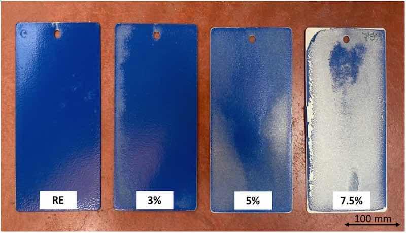 Fig. 1. Cured epoxy coatings with different amounts (from 3 to 7.5 % by wt.) of calcium ion-exchanged silica inhibitor additions, and reference epoxy (RE) coating.
Furthermore, when corrosion protective behavior of thick powder organic coatings is studied, the isolating nature of powder coatings does not allow coating degradation from possible eventual defects to be monitored using traditional electrochemical techniques, such as electrochemical impedance spectroscopy (EIS) [19,33]. For this reason, a localized technique like scanning Kelvin probe (SKP) is used. Although there are published studies of SKP for thin conversion films [34,35] or for liquid coatings [[36], [37], [38]], there is scant literature about their use for thick, highly protective powder coatings [19], which is also another innovative aspect of this article.
This work seeks to enhance the performance of an epoxy-based powder coating, not only to improve its resistance to corrosion, but also to delay a mechanical damage that leaves the metal exposed to corrosive agents.
2. Experimental part
2.1. Manufacturing of the organic coatings
As a reference coating, a commercial epoxy powder paint (labeled RE, “reference epoxy”) was employed, provided by Cubson International (Spain). The anticorrosive microparticles used for the functionalization of the coatings were calcium ion-exchanged silica Shieldex C 303 microparticles (W.R. Grace & Co., USA), with a D50 particle size of 3.6 μm.
In order to optimize the properties and maintain good coverage even on the edges of the pieces, two different percentages of anticorrosive particles were studied 1 and 2 % (by wt.). They were selected because both allow perfect charging of the organic powder particles after the mixing powders, as can be observed in Fig. 2. It can be confirmed that the small appearance problems found on the edges of the samples coated with 3 % particles, which turned into more serious problems for higher amounts of added particles (Fig. 1), do not affect the 1 % and 2 % samples considered in the present study.
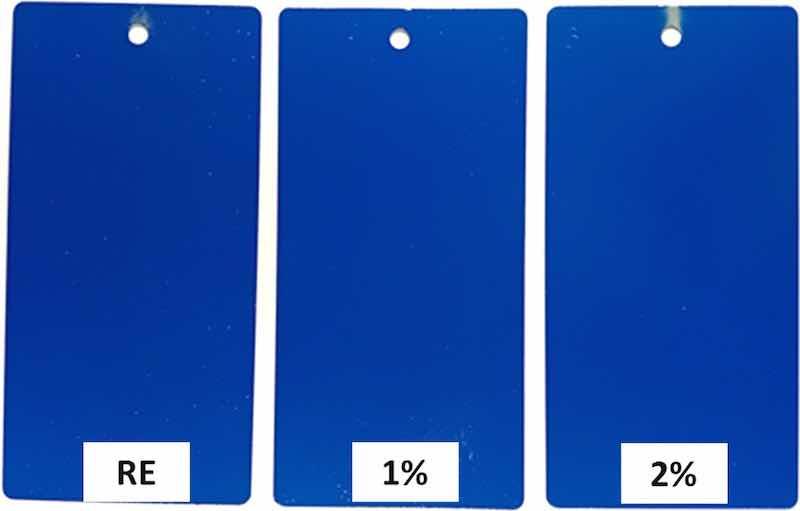 Fig. 2. Comparison of the metal coverage of the cured epoxy coatings used in this study, up to 2 % by wt. calcium-exchanged silica particles.
Silica particles and powder coatings were mixed in two different steps, resorting to a simple procedure: first, a physical premix was carried out in a turbula for 10 min and, subsequently, a hot mixing was carried out in a PolySoft OS (Thermo Fisher Scientific Inc., USA) mixer for 15 min at 67.0 ± 0.1 °C, at 30 rpm and under dry conditions.
Carbon steel sheets (152 × 76 × 0.8 mm3) were degreased before coating. Then, the epoxy-based powders were electrostatic sprayed on steel samples, using a COLO-07 gun with 100 kV voltage source (COLO, China). The next step was curing the coatings at 180 °C for 15 min, following the manufacturer specifications. The thickness of the coatings under study was determined with a thickness gauge (Elcometer 456, Manchester, UK) in different regions of the sample surfaces. All epoxy coatings had similar thicknesses that range between 90 and 100 μm.
2.2. Mechanical and tribological properties
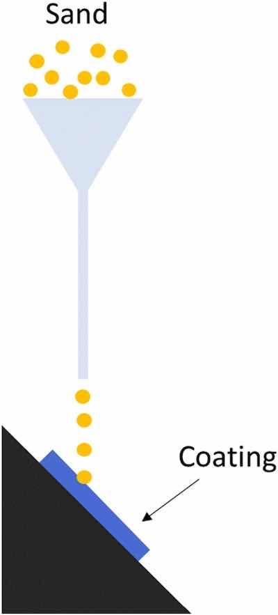 Fig. 3. Scheme of erosive test.With the aim of studying the mechanical performance of the different functionalized coatings, both hardness and wear resistance (both sliding and erosive) were studied.
The universal hardness (HU) and plastic work during indentation (Wplast) were determined using a universal hardness tester (Zwick Roell ZHU 2.5, Germany). The instrumented tester measures the force-indentation depth curve during the test. Wplast is assessed during the application of the load and its removal (as the area between both force-depth curves), and the HU is calculated by dividing the test load by the apparent area of the indentation acquired [39]. The tests were carried out using 5 N load, that was applied at 1 mm/min speed. Each organic coating was measured at least 9 times with this technique.
The reciprocating sliding wear study, under dry conditions, was carried out in a UMT Tribolab reciprocal tribometer (Bruker Optik, USA). The specified parameters were an applied load of 5 N, at a frequency of 10 Hz and a test duration of 10 min. The counter-material used was a 6 mm diameter steel ball. In each coating, 4 wear tracks were made and characterized. Furthermore, the curves plotting the coefficients of friction (μ) evolution with time were obtained for each material for quadruplicate.
The sliding wear tracks were characterized in an Olympus DSX500 opto-digital microscope (Olympus Corporation, Japan). Dimensional characteristics such as average depth were obtained for each wear track, taking at least 12 measurements. In addition, 3D images of the tracks were taken using this same microscope. Finally, scanning electron microscope (SEM) observations of the worn coatings were carried out to obtain information about the deterioration mechanisms, using Teneo-LoVac equipment (Thermo Fisher Scientific Inc., USA). SEM working parameters were 10 kV, a current of 0.4 nA and a working distance of 11.0 ± 0.2 mm.
Erosive wear tests were also carried out under a procedure based on the ASTM D968 standard. The test consists of pouring an abrasive material through a funnel that was directed to the coating to be tested through a vertically placed tube as can be seen in Fig. 3. Specifically, 20 L of normalized sand (with particle size of 1–2 mm) were poured onto a sample placed at 45° from the horizontal. The variation in thickness for each 2 L of sand poured on the coating surface was obtained as a result. In this case, three samples were tested for each type of coating under study. In all cases, the thickness of the coating to be tested was 90–100 μm, and the loss of thickness was always measured just below the funnel, in 7 locations (the center of the stream and 6 points surrounding it). Moreover, thickness measurements in non-tested areas, where sand particles could fall, were completely avoided.
2.3. Influence of immersion in saline solutions on the scratch resistance
The scratch resistance of all organic coatings was evaluated following the advice of EN 13523-12 standard. To do this, an Elcometer 3000 Clemen Unit incision equipment was used. This test mainly consists of holding the coated metal substrate and slowly moving a stylus ball of tungsten carbide to scratch the surface, using a constant load.
The scratch resistance was evaluated according to EN 13523-12 standard. The test was carried out for the three coatings under study in two different conditions: without being exposed to any deteriorating condition (as manufactured), and after being submerged for 7 days in a 3.5 % by weight NaCl solution. The speed of the stylus to make the incision was 35 mm/s and a carbide tungsten tool was used. Four different scratches, until reaching substrate were performed for each coating and each condition. Images were taken using an OLYMPUS SZ-CTV stereo microscope (Olympus Corporation, Japan) and with the Image-Pro Plus 5.0 image analyzer, the delaminated areas (A, mm2) per unit length (L, mm) were measured for each coating. Ten results were obtained for each condition and each material.
2.4. Delamination resistance
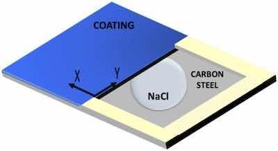 Fig. 4. Scheme of samples used for studying the coating delamination from a defect with SKP.With the aim of studying the delamination between the organic coatings and the carbon steel substrate after a mechanical failure, a localized corrosion study was carried out using the SKP technique. The degradation was obtained through the controlled deposition of a drop of solution on a bare metal region close to bonded coating, and continuous measurement of the corrosion potential, allowing the advance of the delamination front of the system to be determined.
The 3 × 2 cm2 samples were tested, and a 2 × 1 cm2 defect was made with a standard cutting tool. The line that separates the bare metal from the coated one was considered the starting point for the measurements and the starting area of the delamination process (Fig. 4). After making the defect, an electrolyte reservoir was created around the it on the bare substrate using a two-component epoxy adhesive to subsequently be able to deposit the electrolyte without its spilling. The corrosive electrolyte that was used to study the delamination suffered in the coating was 3.5 % by wt. NaCl solution (Fig. 4).
The equipment used was an SKP with height control (Wicinski & Wicinski GmbH, Germany), which performs the measurements keeping the distance between the tip of the probe and the test tube constant depending on the potential signal received. A cylindrical Ni80/Cr20 probe with a 50 μm diameter flat tip was used. The measurements were carried out at 25 °C and in 95 % relative humidity inside the chamber. Tests were carried out on different days after the exposure the electrolyte, from the 1st to the 26th day. A minimum of 4 measurements were considered for each coating and testing time.
Potential measurements were taken at a constant distance between the probe and the coating. 3000 × 500 μm2 regions were swept, using a step size of 50 μm and a movement speed of 4 μm/s. From each voltage map, arithmetic means were calculated to obtain a 2D curve per material and day of potential variation with respect to the scanning distance ‘x’ of the probe (3000 μm). For probe calibration, a standardized Cu/CuSO4 solution was used. It was considered that the delamination front is located at an intermediate point between the start of the intact coating and the metal surface, and its advance is calculated by performing measurements at different exposure times.
3. Results and discussion
3.1. Hardness of coatings
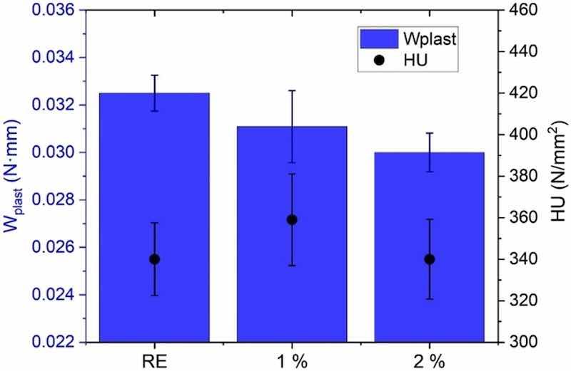 Fig. 5. Effect of the corrosion inhibitor additions on the hardness (HU) and plastic work (Wplast) of the functionalized and non-functionalized epoxies.The hardness results offer a direct information about the curing process of the coating and interesting data that helps to understand the occurrence and progress of corrosion from a defect (Section 3.4).
Fig. 5 displays the results of the universal hardness measurements. The hardness of the RE coating is very similar to those of functionalized coatings. The small amount and their micro-size are limiting factors that do not provide meaningful hardness enhancement. The addition of small amounts of nanoparticles can increase hardness of this coating [12], mainly related to an increased crosslinking of the resin. However, microparticles, such as amorphous silica ones considered in this study, do not promote crosslinking. The interactions between the microparticles (3.6 μm D50) and the epoxy matrix will be much lower than those appearing when nanoparticles are added, due to the considerably lower specific surface of the former particles. The HU seems to be mainly related to that of the matrix, which is a foreseeable fact when such reduced amounts of micro-sized additions (2 %) are considered.
However, the functionalized epoxy coatings seem to lose part of their plasticity with respect to the RE (lower Wplast), as has been previously shown, for example, when alumina microparticles were added to a polyester powder coating through tensile tests [40]. Although the interaction between microparticles and the matrix is small, they can act as points where the stresses concentrate, thus reducing the ductility of the coatings.
3.2. Wear resistance
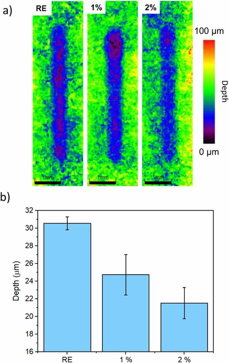 Fig. 6. Results of the sliding wear test on the surface of the studied coatings: a) 3D images of the wear tracks; b) depth of wear tracks.During their in-service exposure, the wear damage of the coatings can take place either by sliding or by erosion. Both types of wear mechanisms can generate local defects on the coating, from which an electrochemical attack can start. Hence, if the coatings are able to limit the appearance of wear defects and the coating is highly isolating, the corrosive attack of the metal base would be effectively hindered.
Regarding the effect of the additions on the sliding wear resistance of the epoxy powder coating, examples of optoelectronic microscopy images of wear tracks can be seen in Fig. 6a. In this figure, the color of the tracks varies according to their depth, following the scale shown to the right of the figure: the purple areas correspond to the deepest region inside the wear tracks, while the green area corresponds to the intact coating. For the RE coating, deep (purple) areas are seen throughout the entire wear tracks, while, for the 2 % coating, shallower (blue) regions are defined in the tracks.
Fig. 6b shows the averaged depth determined for the wear tracks in the different epoxies. Coatings functionalized with corrosion inhibitors have improved their sliding wear resistance, since the depth of the wear track is smaller. It is clear that RE is the coating that wears the most, having an average depth of approximately 30 μm in both cases, while the 1 % has a depth of 22–25 μm, and the 2 % of approximately 20–23 μm.
In addition, in Fig. 7, the time evolution of the coefficient of friction (μ) during the tests is shown. Mainly two different zones can be observed in these curves. The first zone, with μ increasing in a short time, corresponds to the beginning of wear and the first formation of the track. In the second stage, it can be seen that the μ is already nearly constant and corresponds to the progress of wear once the track has been formed [13].
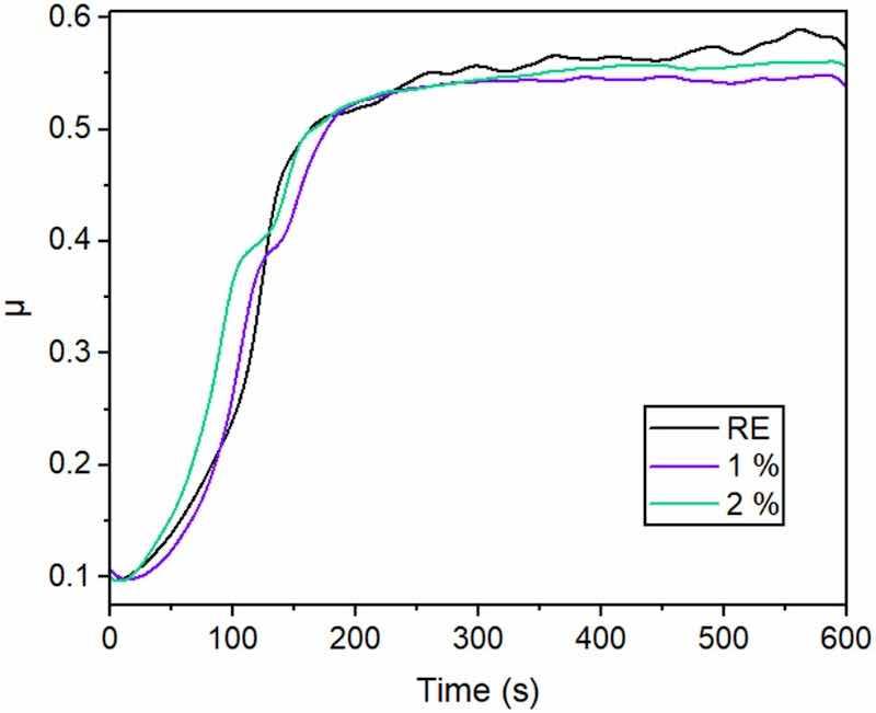 Fig. 7. Examples of the evolution of coefficient of friction (μ) for the three organic coatings under study during reciprocating sliding tests.Comparing the μ curves for the studied coatings, there are no large differences between them. However, there are some small observations that help to understand the influence of the silica inhibitor particles in wear behavior. During the first stage, there is a change in the slope of μ for the functionalized coatings (around 100–150 s), suggesting that the presence of hard silica microparticles make the formation of the wear track slightly more difficult. Furthermore, in the second stage, it can be observed that the RE coating has a somewhat higher μ and has more fluctuations than the coatings with the particles, probably due to more aggressive wear. It has been suggested in previous literature that higher μ values when the track has already been defined correspond to more aggressive wear [41].
The wear mechanism was studied with SEM. The SEM images -with the secondary detector- in the upper row in Fig. 8 show the limit zones of the travel of the counter-material for all epoxy coatings after the tests. In all the materials, the reciprocal movement has caused an accumulation of material at the end of the wear tracks. This is indicative of an abrasive wear mechanism, since it produces a loss of material that does not remain adhered to the coating [5]. On the other hand, in the lower row, the details of the wear tracks -obtained with the backscattered detector- are shown. The different components comprised in the epoxy coatings can also be observed more clearly using this detector. All the coatings have certain base inorganic pigments or charges (TiO2, talc and dolomite for this type of organic coating), which are visualized as white particles. For this reason, it is difficult to distinguish the inhibitory particles in the 1 and 2 % coatings from other ceramic compounds that the commercial powders contain. On the other hand, in all the images, transverse cracks can be seen along the entire worn surface (indicated with red ellipses). These types of cracks are formed in the perpendicular direction of the applied stress or load, and their presence is often observed in materials and structures that have experienced repetitive loading or stress cycles [42]. Those transverse cracks could be related to tensile loadings during this specific sliding test, particularly during the period under higher coefficient of friction.
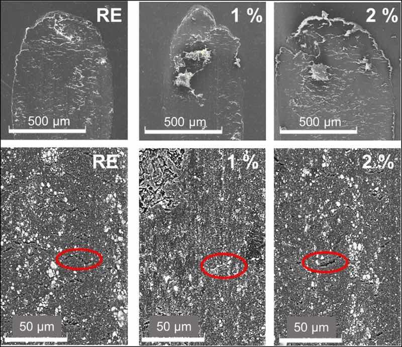 Fig. 8. SEM images of the sliding wear tracks in the organic coatings. From left to right, RE, 1 % and 2 % coatings.
Comparing the images in the lowest row of Fig. 8, there is a higher number of cracks in the RE than in the other two coatings. According to universal hardness results (Fig. 5), silica additions have not increased hardness and even have slightly reduced the plasticity of the coatings (Wplast, Fig. 5). However, their presence has possibly prevented the development of those cracks in the epoxy matrix. The possible cracking of silica microparticles during the wear test could also lead to placing their debris within the cracks, allowing better stress distribution during the wear test and the formation of shallower tracks (Fig. 8). In Fig. 9, it can be observed in detail how pieces of broken microparticles are placed in these cracks, formed during the sliding test. The sliding stresses on the silica particles cause their wearing. This process can provoke their detachment and breakage, and this fine debris can be embedded within the epoxy matrix, filling the cracks and improving stress distribution on the wear track during sliding test.
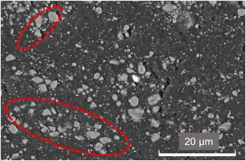 Fig. 9. High-magnification SEM image of the 2 % organic coating wear track.
Erosive wear damages often caused by sand impacts are another place from which the corrosion can start. Fig. 10a shows the typical morphologies of the erosion damages caused by falling sand particles. After carrying out the test, it can be checked that the base metal has not been reached for any coating under study. Naked-eye observation does not show any difference regarding size and shape of the damage. However, local thickness measurements allow finding out an influence of the microparticle additions on erosion wear resistance of coatings. Fig. 10b shows the loss of relative thickness, being all initial thicknesses very similar. RE and 1 % coatings (Fig. 10b) have similar behaviors, losing between 8 and 10 % of the total thickness in all cases at the end of the test. However, the 2 % coating seems to have somewhat more resistance than the other two coatings during the erosion process.
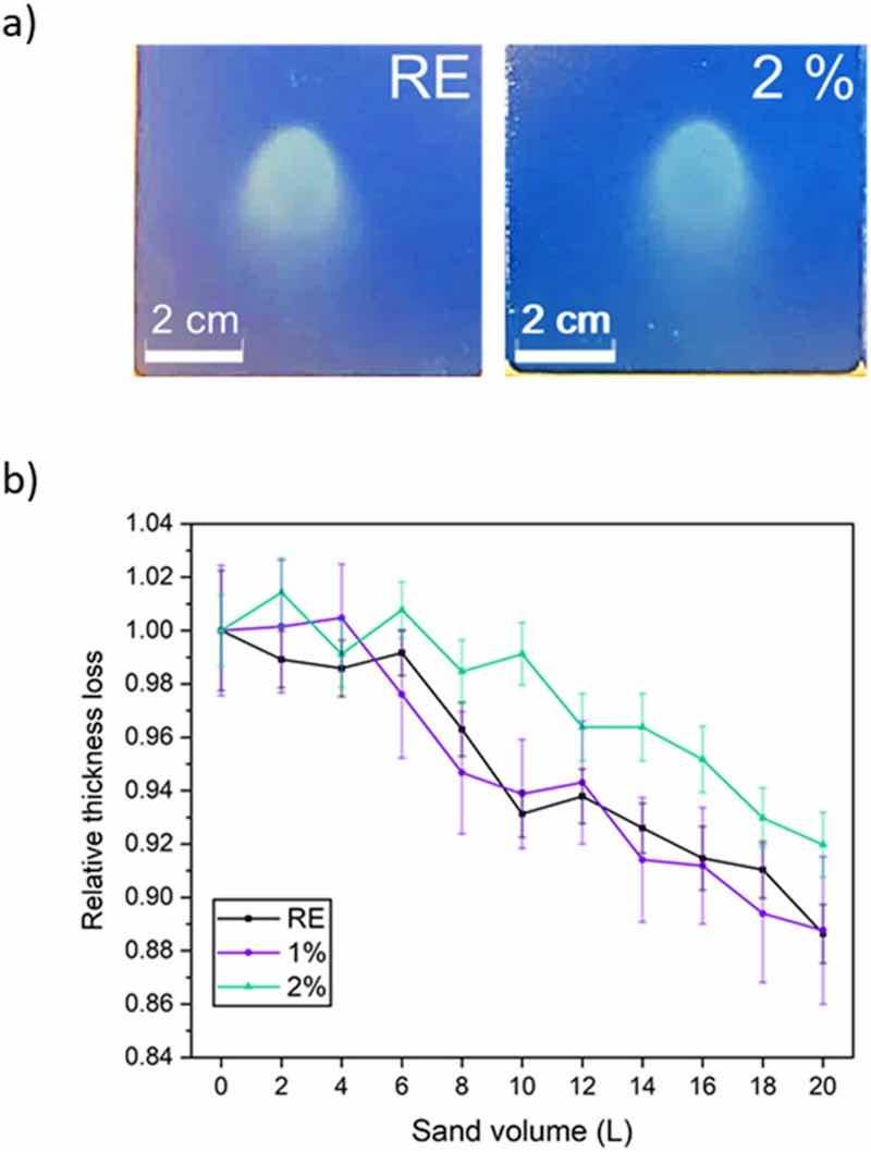 Fig. 10. a) Images of the coatings after the erosion tests. b) Relative thickness loss for all organic coatings when sand is poured causing their erosive wear.The tilting angle (45°) chosen for the erosion test is expected to lead to mixed effects of f deformation and the cutting erosion. Cutting usually appears at high tilting angles (e.g. 60°), with the coating's mechanical properties being the key factor for good erosion performance. However, deformation usually takes place when particles impact [12].
Under the test performed, deformation of the coating should take place initially, which is the main effect of the sand impacts. This first stage can be related to universal hardness results, particularly with the plasticity of the coatings (Wplast, Fig. 5). The coating with most ability to be plastically deformed (i.e., RE coating) will deform its surface in a faster way than the functionalized coatings, with smaller Wplast values. This could lead to a more rapid increase in the roughness of the surface in RE. Then, the cutting erosion will be the dominant wear mechanism, acting on the rough, deformed surface. This cutting would start the loss of thickness of the coating.
Fig. 10b suggests these two mechanisms. Initially thickness losses are minimal, as expected when deformation takes place, and almost no material is removed. This stage is longer for 2 % coating (Fig. 10b), in accordance to its smaller Wplast (Fig. 5). Then, a faster material (thickness) loss takes place, as cutting proceeds. This second stage could be delayed with a harder coating; however, very similar hardness values (Fig. 5) were measured on the three coatings tested, and differences during this second stage of erosive wear (Fig. 10b) do not appear. The first stage is clearly the one that explains the better erosion performance of 2 % coating.
3.3. Scratch resistance
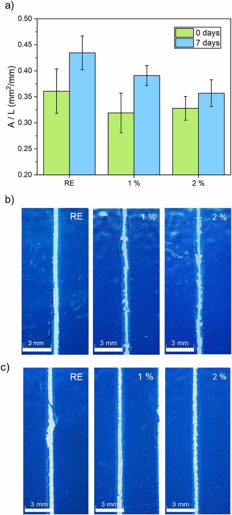 Fig. 11. Scratch test results for all organic coatings. a) Delaminated area before (0 days) and after being submerged for 7 days in a 3.5 % by weight NaCl solution; b) examples of scratch images corresponding to the 0 days test and c) examples of scratch images corresponding to immersed coatings (7 days).Adhesion of the coating to the metal substrate is a key factor to guarantee effective corrosion protection, and the additions should not negatively affect this parameter. Hence, after verifying that the silica inhibitors manage to delay the delamination of the organic coatings, the resistance to mechanical damages through a scratch test was simulated. This scratch study was made in two different conditions: on raw coatings and also after being submerged for 7 days in a 3.5 % by weight NaCl solution. The evaluation of the results according to the detection of an electrical current when substrate was reached during a particular-load scratch, as a method proposed in EN 13523–12 standard, was not possible, as this approach does not work for hard coatings such as those studied in this work (Fig. 5). Alternative quantification methods are proposed in that standard, as the load just prior to penetration, or a pass/fail method with a specified load. For all the coatings under study, immersed and non-immersed, the 4 kg load did not penetrate in the coating deep enough to the ball making contact with the metallic substrate. However, with 5 kg, a full scratch was obtained in all the length (76 mm), fully penetrating down to the steel substrate from the initial scratching point. However, though this load range do not offer any relevant information that allow to discriminate among the coatings under study, some quantified information can be obtained from the analysis of the scratches performed using 5 kg load.
The results of the tests carried out at 5 kg load can be seen in Fig. 11. After performing the scratches, the free substrate area was measured to quantify the scratch resistance of all organic coatings. Quantification of the damage was done measuring the delaminated area (A), i.e. the area where tungsten carbide stylus deepened to the substrate, per unit length (L) of scratch. The delaminated area after the scratch test was measured after taking images of all the scratches like those shown in Fig. 11b (raw coatings) and Fig. 11c (7 days immersed coatings). The quantification of the scratch damage of each experiment and each coating is shown in Fig. 11a.
Comparing the as-manufactured organic coatings, all of them present a similar adherence to the metal substrate, demonstrating that the presence of ceramic microparticles has neither weakened the bonds of the epoxy with the steel, nor strengthen them. The coatings that have not been submerged (Fig. 11a) exhibit less delamination and, consequently, stronger adhesion to the metal substrate than the ones that have suffered immersion, as could be expected. The permeated water and ions affect the bonds formed between the polymer and the metal, which have a polar nature. After the immersion in the saline solution, the better performance of the coatings with ion-exchanged silica particles becomes evident, with the coating that has the highest amount of additions experiencing the lowest loss of adhesion due to immersion. These results are also consistent with the images in Fig. 11b and c. In both raw and immersed coatings, the scratches on the RE coating appear notably straighter and wider, closely resembling the shape of the test tip. In the functionalized coatings, the delaminated area is smaller, as evidenced by the fact that the scratch test tip has not managed to remove the entire coating. It is observed that the delaminated areas are greater in the organic coatings submerged for 7 days (Fig. 11b) when compared to those for 0 days (Fig. 11c). Moreover, scratches on functionalized coatings seem to be straighter after immersion (particularly clear for 1 % coating), as a result of the loss of adhesion after the immersion in NaCl solution. Hence, when the tungsten carbide stylus scratches these coatings, the material can be removed easier than in the raw coatings, and narrowings are not found in the scratch. This indicates that some of the coating remains firmly attached to the metal, resulting in stronger adhesion between the metal and the coating.
Chloride ions are, at least partially, retained in silica particles due to their cation-exchange capability, and so, the solution reaching the metal/coating interface is less aggressive. Moreover, a partial dissolution of silica particles with the permeated water, and the precipitation of calcium silicate layer in metal-coating interface occurring after this dissolution [26,27,29] can also reduce the negative effect that the immersion has on the coating adherence.
The small amount of particles used (1 or 2 %) can assure a continuous polymeric network, not affecting the epoxy curing process (as hardness tests shown in Fig. 5 inform). Scratch tests suggest that this cation-exchange capability of the pigments takes place [28,43], thus reducing the negative effect of immersion on coating adhesion.
3.4. Delamination resistance
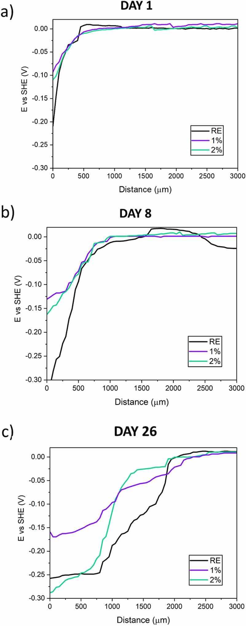 Fig. 12. Examples of SKP profiles of all organic coatings at different exposure times: a) 1, b) 8 and c) 26 days.The corrosion of coated metal substrate often starts from a local defect in the coating, from a wear process, for instance. The SKP results make it possible to study the rate and mechanism of the loss of adhesion suffered by the organic coatings under a 3.5 wt% NaCl solution after a mechanical damage. Fig. 12 shows the time evolution of the SKP voltage profiles since the electrolyte was placed and their time evolution (days 1, 8 and 26).
In these curves, three different zones can be distinguished, with their shape suggesting that the corrosion attack occurs through a cathodic delamination process [32,36]. Starting from 0 distance, the first zone of the SKP curves corresponds to the potential of the carbon steel exposed through the defect to the electrolyte. This region registers low values, indicating that the substrate acts as an anodic zone in the system. This zone becomes wider when the delamination between the coating and the substrate increases. On the other hand, the right area in the curves (last part of the SKP curves) corresponds to the undamaged organic coating. In this latter area, where the potentials are close to 0 V, organic coatings still remain perfectly adhered. In addition, there is an intermediate zone between the two previous ones (the one corresponding to the bare steel and one to the undamaged coating), which represents the zone of cathodic activity that takes place under the organic coatings and causes its loss of adherence and coating delamination.
After 1 day of testing (Fig. 12a), all the materials show similar behavior, since delamination is a slow process in strongly adherent, low-permeable coatings, and longer exposures are needed to begin to see this process. In Fig. 12b, a certain difference between the functionalized coatings and the RE can already be observed, since the delamination front has shifted for the RE more than for the other two coatings. However, on the last day of the SKP test (Fig. 12c), the greatest differences between coatings are observed, since the widest anodic zone is clearly defined for the RE, due to the highest displacement of its cathodic delamination front.
The cathodic region, as has been previously indicated, is located between the potential of the steel and the 0 V potential of the perfectly adhered coating. In Fig. 13, the progress of delamination has been plotted, considering that the front is located in the midpoint of the cathodic zone with activity [44]. It can be observed that, until the 8th day, there are just small differences in the performance of all the coatings, as Fig. 12a and b also show. Then, as of that day, the 1 % and 2 % coatings have less delamination than the RE coating. When the last day of the test is reached, it can be noted how the differences in the delamination front are much higher, since the RE delaminates up to almost 2000 μm, while the functionalized coatings with silica delaminate slightly more than half the RE delaminates. The 3 % coating has better resistance to delamination (around 750 μm on the last day), as it has been previously reported [32]. Therefore, taking these results into account, it is clear that adding a small proportion of the calcium ion-exchanged silica particles acts positively against the progress of the corrosive attack from the defect under the coating, showing around a 45–50 % reduction in the delaminated distance compared to RE. Bearing in mind that the reduction in this parameter achieved with 3 % additions is about 60–65 % [32], and the improvement achieved in the coverage with 2 % coatings (Fig. 2), the formulation analyzed in the present study can be considered an advantageous option for certain applications.
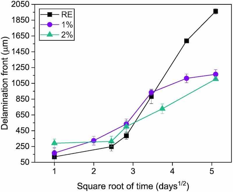 Fig. 13. Progress of delamination front from the defect for all organic coatings during SKP measurements.There are previous studies that explain this cathodic delamination mechanism for non-functionalized coatings [45,46]. For steel with defective coatings, the advance of the delamination front is assumed to be controlled exclusively by the diffusion of Na+ cations from the solution on the anode to the cathode. The drop deposited in the anodic area in contact with the coating makes the metal under the partially detached coating able to act as a cathode because of the O2 diffused through the polymer [47]. The traditional good O2 permeability of the polymers would make the region under the detached coating oxygen-richer than that covered by the solution and the corrosion products where the anode is located. The high cathodic activity taking place under the coating favors the high concentration of OH− ions in these regions. Hydroxyl ions cause gradual adhesion failure at the substrate-coating interface, chemically weakening the epoxy-metal bonds responsible for the coating adhesion. Then a linear relationship should be found between the advance of the delamination front and the square root of time [45,48]. However, this relationship cannot be found for the data in Fig. 13. In recent published literature [19,49,50], it has been proven that, if organic coatings have much greater thicknesses or with certain corrosion inhibitors, the O2 diffusion through the polymer is more hindered and deviations for that kinetics can be found. In these cases, the delamination mechanism would be controlled, not only by the Na+ diffusion, but it is also influenced by the diffusion of oxygen through of the coating. For the coatings under study, whose thickness is high (between 90 and 100 μm), the influence of the O2 diffusion through the coatings in the kinetics must be borne in mind.
As has been observed in Fig. 12, Fig. 13, the calcium ion-exchanged silica corrosion inhibitors used clearly hinder the development of the corrosion under the coating from a defect. The primary mechanism for corrosion protection using this type of inhibitors arises from the creation of a protective calcium silicate film or layer at the interface between the organic coating and the metal, as can be seen in other previously reported studies works on liquid coatings [26,27,29]. This layer is formed at the interface when there is previous presence of water and/or aggressive ions, which are what cause the ions, in this case of calcium and silicon, to be released. In this way, this non-conductive layer is placed between the anodic zone and the cathodic zone of the metal, slowing down the Na+ movement from the anode to the cathode and delaying the progress of the attack as can also be observed in this work. The time necessary to observe meaningful differences among functionalized coatings and RE could be related to the time required for the electrolyte to dissolve the added particles and form the protective layer in the metal-coating interphase. Another complementary explanation can be related to Cl−-trapping ability inhibitor.
The results obtained for the previously submerged coatings (Fig. 11) can also be correlated with the SKP results (Fig. 12, Fig. 13). Although there is no previous mechanical damage in the immersed, scratch-tested samples, the ion-exchanged silica particles also seem to play the role, forming a protective layer on the metal-coating interface after water-exposure [26] and/or trapping chlorides diffusing through the coating before they reach the metal surface by an ion-exchange mechanism [25]. Both mechanisms have been demonstrated in liquid organic coatings with much higher amounts of additions, but the results presented in this paper prove that they are also effective for thick, protective powder coatings in spite of also being added in low amounts, not to affect the formation and properties of the epoxy coating (Fig. 2). The beneficial effects of these additions are also complemented by the protective effect that the ceramics additions have shown against sliding wear (Fig. 6), as the presence of silica particles and their debris in the wear tracks slow down their progress (Fig. 8, Fig. 9). Moreover, the additions also have a positive effect against erosive wear (Fig. 10b) as the additions decrease the plasticity of the coating (Fig. 5).
4. Conclusions
In this work, new epoxy powder with calcium ion-exchanged silica particles have been manufactured by hot mixing without showing any relevant coverage problem during their application on steel samples. Thanks to this functionalization, resistance to delamination, scratch resistance and sliding wear resistance have been improved when compared to the raw commercial coating. The following conclusions have been drawn from this study:
- By adding 1 or 2 % of calcium ion-exchanged silica, it has been possible to reduce the cathodic delamination of epoxy powder coatings after mechanical damage. The inhibitory particles, despite their reduced amount, have proven to be effective.
- The inhibitor additions do not affect either the adhesion or the hardness of the as-manufactured coatings, as no detrimental effect has been observed for these properties. A small decrease of the Wplast of the coatings is observed, especially for coatings with 2 % silica microparticles.
- Scratch resistance of coatings after immersion in a NaCl solution shows the positive effect of added inhibitors, as they are able to exchange cations with the uptaken saline solution. The loss of adhesion of functionalized coatings is smaller than that of reference epoxy coating.
- Better sliding wear resistances are obtained for coatings with 1 and 2 % additions. The debris of cracked micro-sized inhibitors locates in the cracks of epoxy matrix, reducing the wear process.
- No detrimental effect of the micro particles additions in the erosion resistance is observed and the 2 % suffers lower thickness loss, probably because its lower plasticity delays the deformation stage during the erosion test.
Written by María Fernández-Álvareza, Francisco Velascob, Daniel de la Fuentec, and Asunción Bautistab
- a: Electroceramic Department, Instituto de Ceramica y Vidrio (ICV), CSIC, Kelsen 5, 28049 Madrid, Spain
- b: Department of Materials Science and Engineering, IAAB, Universidad Carlos III de Madrid, Avda. Universidad 30, 28911 Leganés, Madrid, Spain
- c: Centro Nacional de Investigaciones Metalurgicas (CENIM), CSIC, Avda. Gregorio del Amo 8, 28040 Madrid, Spain
Credit authorship contribution statement:
- María Fernández-Álvarez: Conceptualization, Data curation, Formal analysis, Funding acquisition, Investigation, Methodology, Resources, Validation, Visualization, Writing – original draft.
- Francisco Velasco: Conceptualization, Formal analysis, Funding acquisition, Investigation, Methodology, Resources, Supervision, Validation, Writing – review & editing.
- Daniel de la Fuente: Data curation, Formal analysis, Investigation, Validation, Writing – review & editing.
- Asunción Bautista: Conceptualization, Formal analysis, Funding acquisition, Investigation, Methodology, Resources, Supervision, Validation, Writing – review & editing.
Declaration of competing interest: The authors declare that they have no known competing financial interests or personal relationships that could have appeared to influence the work reported in this paper.
Acknowledgements: M.F.A. acknowledges financial support from the Ministerio de Universidades (MIU) grant for Requalification of the Spanish University System for 2021–2023, of the Universidad Carlos III de Madrid, of July 1, 2021 and MCIN/AEI/10.13039/501100011033 and European Union NextGeneration EU/PRTR (Grant No FJC2021-047888-I).
References
[1] M. Iannuzzi, G.S. Frankel, The carbon footprint of steel corrosion, npj Mater. Degrad. 6 (2022) 1–4, https://doi.org/10.1038/s41529-022-00318-1.
[2] A. Fihri, D. Abdullatif, H. Bin Saad, R. Mahfouz, H. Al-Baidary, M. Bouhrara, Decorated fibrous silica epoxy coating exhibiting anti-corrosion properties, Prog. Org. Coat. 127 (2019) 110–116, https://doi.org/10.1016/j.porgcoat.2018.09.025.
[3] M.G. Hosseini, M. Jafari, R. Najjar, Effect of polyaniline–montmorillonite nanocomposite powders addition on corrosion performance of epoxy coatings on Al 5000, Surf. Coat. Technol. 206 (2011) 280–286, https://doi.org/10.1016/j. surfcoat.2011.07.012.
[4] X. Zhang, F. Wang, Y. Du, Effect of nano-sized titanium powder addition on corrosion performance of epoxy coatings, Surf. Coat. Technol. 201 (2007) 7241–7245, https://doi.org/10.1016/j.surfcoat.2007.01.042.
[5] M. Fern´ andez-´ Alvarez, F. Velasco, A. Bautista, Epoxy powder coatings hot mixed with nanoparticles to improve their abrasive wear, Wear 448–449 (2020) 203211, https://doi.org/10.1016/j.wear.2020.203211.
[6] C.X. Wang, Y.Y. Han, W. Wang, J. Liu, N. Wang, B.R. Hou, Polyvinyl chloride/ epoxy double layer powder coating enhances coating adhesion and anticorrosion protection of substrate, Prog. Org. Coat. 158 (2021) 106335, https://doi.org/ 10.1016/j.porgcoat.2021.106335.
[7] M. Barletta, L. Lusvarghi, F. Pighetti Mantini, G. Rubino, Epoxy-based thermosetting powder coatings: surface appearance, scratch adhesion and wear resistance, Surf. Coat. Technol. 201 (2007) 7479–7504, https://doi.org/10.1016/j. surfcoat.2007.02.017.
[8] A. Husain, J. Chakkamalayath, S. Al-Bahar, Electrochemical impedance spectroscopy as a rapid technique for evaluating the failure of fusion bonded epoxy powder coating, Eng. Fail. Anal. 82 (2017) 765–775, https://doi.org/10.1016/j. engfailanal.2017.06.041.
[9] M. Aghili, M.K. Yazdi, Z. Ranjbar, S.H. Jafari, Anticorrosion performance of electro-deposited epoxy/ amine functionalized graphene oxide nanocomposite coatings, Corros. Sci. 179 (2021) 109143, https://doi.org/10.1016/j. corsci.2020.109143.
[10] B. Pilch-Pitera, M. Kędzierski, E. Olejnik, S. Zapotoczny, Structure and properties of polyurethane-based powder clear coatings systems modified with hydrotalcites, Prog. Org. Coat. 95 (2016) 120–126, https://doi.org/10.1016/j. porgcoat.2016.03.009.
[11] M. Kalaee, S. Akhlaghi, A. Nouri, S. Mazinani, M. Mortezaei, M. Afshari, D. Mostafanezhad, A. Allahbakhsh, H.A. Dehaghi, A. Amirsadri, D.P. Gohari, Effect of nano-sized calcium carbonate on cure kinetics and properties of polyester/epoxy blend powder coatings, Prog. Org. Coat. 71 (2011) 173–180, https://doi.org/ 10.1016/j.porgcoat.2011.02.006.
[12] M. Fern´ andez-´ Alvarez, F. Velasco, A. Bautista, J. Abenojar, Effect of silica nanoparticles on the curing kinetics and erosion wear of an epoxy powder coating, J. Mater. Res. Technol. 9 (2020), https://doi.org/10.1016/j.jmrt.2019.10.073.
[13] M. Fern´ andez-´ Alvarez, F. Velasco, A. Bautista, F.C.M. Lobo, E.M. Fernandes, R. L. Reis, Manufacturing and characterization of coatings from polyamide powders functionalized with nanosilica, Polymers 12 (2020) 2298, https://doi.org/ 10.3390/polym12102298.
[14] J. Radziejewska, J. Grzelka, Effect of concentration GO and diamond wax and method of introducing additives on morphology and properties of epoxy powder coating, Polym. Test. 117 (2023) 107866, https://doi.org/10.1016/j. polymertesting.2022.107866.
[15] S. Chen, C. Yin, Y. Wang, S. Yi, X. Gao, X. Zhang, Q. Liao, Y. Zhang, X. Zhao, J. Rao, B. Hou, Developing polydopamine modified molybdenum disulfide/epoxy resin powder coatings with enhanced anticorrosion performance and wear resistance on magnesium lithium alloys, J. Magnes. Alloys 10 (2022) 2534–2545, https://doi. org/10.1016/j.jma.2021.08.007.
[16] M. Zouari, M. Kharrat, M. Dammak, M. Barletta, Scratch resistance and tribological performance of thermosetting composite powder coatings system: a comparative evaluation, Surf. Coat. Technol. 263 (2015) 27–35, https://doi.org/10.1016/j. surfcoat.2014.12.066.
[17] J. Zhang, G. Kong, S. Li, Y. Le, C. Che, S. Zhang, D. Lai, X. Liao, Graphene- reinforced epoxy powder coating to achieve high performance wear and corrosion resistance, J. Mater. Res. Technol. 20 (2022) 4148–4160, https://doi.org/10.1016/ j.jmrt.2022.08.156.
[18] F. Andreatta, A. Rondinella, M. Zanocco, G. Capurso, R. Vendramin, A. Guarino, L. Fedrizzi, Corrosion, electrical and thermal behaviour of graphene modified polyester powder coatings, Prog. Org. Coat. 179 (2023) 107517, https://doi.org/ 10.1016/j.porgcoat.2023.107517.
[19] M. Fern´ andez-´ Alvarez, F. Velasco, A. Bautista, Y. Gonzalez, Corrosion protection in chloride environments of nanosilica containing epoxy powder coatings with defects, J. Electrochem. Soc. 167 (2020) 1–25, https://doi.org/10.1149/1945- 7111/abd003.
[20] D. Piazza, A.F. Baldissera, S.R. Kunst, E.S. Rieder, L.C. Scienza, C.A. Ferreira, A. J. Zattera, Influence of the addition of montmorillonite in an epoxy powder coating applied on carbon steel, Mater. Res. 18 (2015) 897–903, https://doi.org/10.1590/ 1516-1439.312714.
[21] E. Huttunen-Saarivirta, G.V. Vaganov, V.E. Yudin, J. Vuorinen, Characterization and corrosion protection properties of epoxy powder coatings containing nanoclays, Prog. Org. Coat. 76 (2013) 757–767, https://doi.org/10.1016/j. porgcoat.2013.01.005.
[22] M.F. Montemor, Functional and smart coatings for corrosion protection: a review of recent advances, Surf. Coat. Technol. 258 (2014) 17–37, https://doi.org/ 10.1016/j.surfcoat.2014.06.031.
[23] M. Yeganeh, M. Omidi, T. Rabizadeh, Anti-corrosion behavior of epoxy composite coatings containing molybdate-loaded mesoporous silica, Prog. Org. Coat. 126 (2019) 18–27, https://doi.org/10.1016/j.porgcoat.2018.10.016.
[24] Y. Yin, H. Zhao, M. Prabhakar, M. Rohwerder, Organic composite coatings containig mesoporus silica particles: degradation of the SiO2 leading to sefthealing of the delaminated interface, Corros. Sci. 200 (2022) 110252, https://doi.org/ 10.1016/j.corsci.2022.110252.
[25] E. Shchukina, D. Shchukin, D. Grigoriev, Halloysites and mesoporous silica as inhibitor nanocontainers for feedback active powder coatings, Prog. Org. Coat. 123 (2018) 384–389, https://doi.org/10.1016/j.porgcoat.2015.12.013.
[26] T. Fletcher, Ion-exchanged silica anticorrosive pigments: a review and recent developments, JCT CoatingsTech 10 (2013) 28–39.
[27] R. Romagnoli, M. Deya, B. del Amo, The mechanism of the anticorrosive action of calcium-exchanged silica, Surf. Coat. Int. B: Coat. Trans. 86 (2003) 135–141, https://doi.org/10.1007/BF02699625.
[28] J.M. Vega, N. Granizo, J. Simancas, D. De La Fuente, I. Díaz, M. Morcillo, Corrosion inhibition of aluminum by organic coatings formulated with calcium exchange silica pigment, J. Coat. Technol. Res. 10 (2013) 209–217, https://doi.org/ 10.1007/s11998-012-9440-8.
[29] N. Granizo, J.M. Vega, D. De La Fuente, B. Chico, M. Morcillo, Ion-exchange pigments in primer paints for anticorrosive protection of steel in atmospheric service: anion-exchange pigments, Prog. Org. Coat. 76 (2013) 411–424, https:// doi.org/10.1016/j.porgcoat.2012.10.009.
[30] L.W. Vasconcelos, I.C.P. Margarit, O.R. Mattos, F.L. Fragata, A.S.B. Sombrad, Inhibitory properties of calcium exchanged silica epoxy paintings, Corros. Sci. 43 (2001) 2291–2303, https://doi.org/10.1016/S0010-938X(01)00037-3.
[31] F. Deflorian, S. Rossi, M. Fedel, L.G. Ecco, R. Paganica, M. Bastarolo, Study of the effect of corrosion inhibitors on powder coatings applied on steel, Prog. Org. Coat. 77 (2014) 2133–2139, https://doi.org/10.1016/j.porgcoat.2014.03.014.
[32] M. Fern´ andez- ´ Alvarez, C. Hij´ on-Montero, A. Bautista, F. Velasco, D. de la Fuente, The effect of additions of anticorrosive pigments on the cathodic delamination and wear resistance of an epoxy powder coating, Prog. Org. Coat. 173 (2022), https:// doi.org/10.1016/j.porgcoat.2022.107165.
[33] F. Mahdavi, M. Forsyth, M.Y.J. Tan, Techniques for testing and monitoring the cathodic disbondment of organic coatings: an overview of major obstacles and innovations, Prog. Org. Coat. 105 (2017) 163–175, https://doi.org/10.1016/j. porgcoat.2016.11.034.
[34] R. Posner, N. Fink, G. Giza, G. Grundmeier, Corrosive delamination and ion transport along stretch-formed thin conversion films on galvanized steel, Surf. Coat. Technol. 253 (2014) 227–233, https://doi.org/10.1016/j. surfcoat.2014.05.041.
[35] T. Lostak, C. Timma, S. Krebs, J. Flock, S. Schulz, Organosilane modified Zr-based conversion layer on Zn–Al alloy coated steel sheets, Surf. Coat. Technol. 305 (2016) 223–230, https://doi.org/10.1016/j.surfcoat.2016.08.030.
[36] N.W. Khun, G.S. Frankel, Cathodic delamination of polyurethane/multiwalled carbon nanotube composite coatings from steel substrates, Prog. Org. Coat. 99 (2016) 55–60, https://doi.org/10.1016/j.porgcoat.2016.05.002.
[37] C. Zea, R. Barranco-García, J. Alc´ antara, B. Chico, M. Morcillo, D. de la Fuente, Hollow mesoporous silica nanoparticles loaded with phosphomolybdate as smart anticorrosive pigment, J. Coat. Technol. Res. 14 (2017) 869–878, https://doi.org/ 10.1007/s11998-017-9924-7.
[38] T.D. Singewald, T.M. Bruckner, R. Gruber, G. Schimo-Aichhorn, L. Hader-Kregl, S. Poeller, M. Mueller, C. Kern, G. Luckeneder, K.H. Stellnberger, B. Strauß, M. Hafner, M. Valtiner, Water-uptake in hollow glass microspheres and their influence on cathodic and anodic delamination along the polymer/metal-interface, Corros. Sci. 196 (2022) 2–11, https://doi.org/10.1016/j.corsci.2021.110045.
[39] F. Velasco, G. Blanco, A. Bautista, M.A. Martínez, Effect of welding on local mechanical properties of stainless steels for concrete structures using universal hardness tests, Constr. Build. Mater. 23 (2009) 1883–1891, https://doi.org/ 10.1016/j.conbuildmat.2008.09.025.
[40] S.M. Mirabedini, A. Kiamanesh, The effect of micro and nano-sized particles on mechanical and adhesion properties of a clear polyester powder coating, Prog. Org. Coat. 76 (2013) 1625–1632, https://doi.org/10.1016/j.porgcoat.2013.07.009.
[41] M. Fern´ andez-´ Alvarez, F. Velasco, A. Bautista, B. Galiana, Functionalizing organic powder coatings with nanoparticles through ball milling for wear applications, Appl. Surf. Sci. 513 (2020) 145834, https://doi.org/10.1016/j. apsusc.2020.145834.
[42] M. Fern´ andez-´ Alvarez, F. Velasco, M. Torres-Carrasco, A. Bautista, Hindering the decrease in wear resistance of UV-exposed epoxy powder coatings by adding nano- SiO2 through ball milling, Wear 480–481 (2021), https://doi.org/10.1016/j. wear.2021.203935.
[43] F. Deflorian, I. Felhosi, Electrochemical impedance study of environmentally friendly pigments in organic coatings, Corrosion 59 (2003) 112–120, https://doi. org/10.5006/1.3277540.
[44] A. Leng, H. Streckel, M. Stratmann, The delamination of polymeric coatings from steel. Part 1: calibration of the kelvin probe and basic delamination mechanism, Corros. Sci. 41 (1998) 547–578, https://doi.org/10.1016/S0010-938X(98)00166- 8.
[45] H. Bi, J. Sykes, Cathodic delamination of unpigmented and pigmented epoxy coatings from mild steel, Prog. Org. Coat. 90 (2016) 114–125, https://doi.org/ 10.1016/j.porgcoat.2015.10.002. M. Fern´ andez-´ Alvarez et al. Surface & Coatings Technology 477 (2024) 130377 11
[46] A. Nazarov, M.G. Olivier, D. Thierry, SKP and FT-IR microscopy study of the paint corrosion de-adhesion from the surface of galvanized steel, Prog. Org. Coat. 74 (2012) 356–364, https://doi.org/10.1016/j.porgcoat.2011.10.009.
[47] N.W. Khun, G.S. Frankel, Effects of surface roughness, texture and polymer degradation on cathodic delamination of epoxy coated steel samples, Corros. Sci. 67 (2013) 152–160, https://doi.org/10.1016/j.corsci.2012.10.014.
[48] C.F. Glover, C.A.J. Richards, J. Baker, G. Williams, H.N. McMurray, In-coating graphene nano-platelets for environmentally-friendly corrosion protection of iron, Corros. Sci. 114 (2017) 169–172, https://doi.org/10.1016/j.corsci.2016.11.009.
[49] C.F. Glover, C.A.J. Richards, G. Williams, H.N. McMurray, Evaluation of multi- layered graphene nano-platelet composite coatings for corrosion control part II – cathodic delamination kinetics, Corros. Sci. 136 (2018) 304–310, https://doi.org/ 10.1016/j.corsci.2018.03.014.
[50] B. Andreon, B.L. Guenther, W.L. Cavalcanti, L. Colombi Ciacchi, P. Plagemann, On the use of scanning Kelvin probe for assessing in situ the delamination of adhesively bonded joints, Corros. Sci. 157 (2019) 11–19, https://doi.org/10.1016/ j.corsci.2019.03.001.