
In contrast to plating or electrodeposition of coatings onto a substrate, an important surface finishing technology involves the removal of material from a substrate.
Some specific examples of material removal surface finishing technologies include electropolishing, electrochemical deburring and electrochemical through-mask etching. This paper presents a brief introduction to the electrochemical principals involved in conventional electrolytic electropolishing, which generally utilize high viscosity and high resistivity concentrated acid electrolytes.
The bulk of the paper will focus on a recent approach to electropolishing/electroetching, based on pulse/pulse reverse electrolysis in low concentration/low viscosity aqueous electrolytes. A number of pulse/pulse reverse electropolishing and electroetching development activities, ranging from automotive planetary gears to fluid control valves to medical stents to superconducting radio-frequency cavities and materials including carbon steel, stainless steel, nickel/titanium-based alloys, and niobium will be described.
Introduction
 Figure 1 - (a) Generalized surface roughness and (b) electropolishing by removal of asperities.Electropolishing and electrochemical deburring are industrially important edge and surface finishing technologies. Applications include (1) deburring of carbon steel automotive planetary gears, (2) polishing of stainless steel fluid control valves, (3) polishing of nickel-titanium medical implant stents and (4) polishing of niobium superconducting radio-frequency cavities for high energy physics applications. An emerging derivative technology with numerous industrial applications is electrochemical through-mask etching.
Conventional surface finishing technologies utilize high viscosity and/or low conductivity electrolytes, such as concentrated acids (e.g., sulfuric, phosphoric) and non-aqueous solutions (ethylene glycol, methanol-sulfuric acid).1 For strongly passive materials (e.g., titanium and titanium alloys and niobium), hydrofluoric acid is added to the electrolyte to depassivate the surface.2,3,4
Alternatively, some have suggested electropolishing strongly passive materials in acid-alcohol electrolytes with low water content5 or organic solutions containing fluoride salts.6 Due to the nature of conventional edge and surface finishing electrolytes, process control and robustness are difficult7 and reject rates are often as high as 40 to 50%.8,9
Background and Technical Approach
Conventional electropolishing
As depicted in Fig. 1(a), on some scale, all surfaces are rough. Electropolishing is the process whereby the asperities are preferentially removed by an electrolytic reaction [Fig. 1(b)], generally represented as:
M0 → M+n +ne- (1)
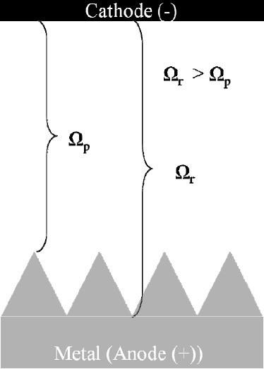 Figure 2 - Focusing electric field on surface asperities in low conductivity electrolytes.Low conductivity electrolytes, such as ethylene glycol may be used to focus the electric field on surface asperities as illustrated in Fig. 2. As the electrolyte resistance is increased, the voltage gradient between the asperities and the recesses becomes greater and the asperities are preferentially removed. High resistance electrolytes have been particularly reported for electrochemical deburring applications. Due to the high electrolyte resistance required to focus the current field on the peaks, excessive heating of the electrolyte is often observed and there is a need for chilling during processing. Even with active chilling, during production trials for deburring automotive parts using an ethylene glycol electrolyte with ammonium salt additions, Ford Motor Co. reported excessive heat leading to an unacceptable ammonia odor, limited cathode lifetime, and that the electrolyte was difficult to maintain and expensive to replace.7
As illustrated in Fig. 3, high viscosity electrolytes are used in conventional electropolishing processes to focus the electric field on surface asperities. For given electrolyte agitation conditions, the diffusion layer thickness (δ) is proportional to the electrolyte viscosity. For diffusion layer thicknesses greater than the characteristic dimension of the surface roughness, under mass transport control, the currents will be higher at the asperities than the recesses and the asperities are preferentially removed. Jacquet first reported that the optimum region for electropolishing is the mass transport or current limited plateau in the polarization curve.10 Subsequently, Wagner reported “microprofile” leveling under mass transport limited conditions for the case of large diffusion layers.11 The diffusion-limited process has been attributed to diffusion of the dissolved metal ion away from the polished surface12 or the diffusion of an “acceptor ion” or complexing/solvating species to the polished surface.13 These diffusion-limited processes are further hindered, and hence electropolishing improved, by the formation of a viscous salt film in the recesses of the surface.1
During anodic metal dissolution (Eq. 1) some metal surfaces can form a passive oxide film, generally described as:
M + xH2O → M(Ox) + 2xH+ + 2xe- (2)
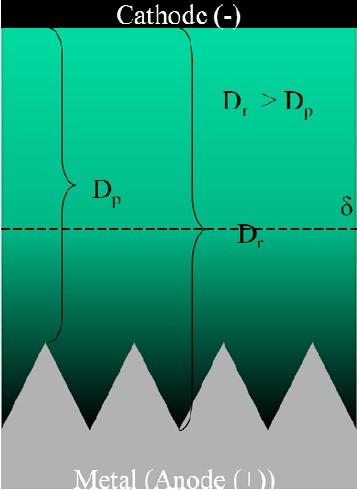 Figure 3 - Focusing electric field on surface asperities in high viscosity electrolytes.For these strongly passivating metals (stainless steel 300 series, titanium and nickel and their alloys among other materials), continued electropolishing leads to a roughened surface similar to pitting corrosion. Consequently, for some of these materials, hydrofluoric acid is added to the electrolyte to depassivate the metal surface by forming soluble metal fluorides and/or metal oxyfluorides.2,3 Considerable process control issues as well as safety issues are associated with managing and handling these hydrofluoric acid-containing electrolytes.
In summary, conventional electropolishing processes using concentrated viscous acid electrolytes and/or resistive electrolytes and/or hydrofluoric acid electrolytes along with various chemical additives are complex and difficult to control. In the case of niobium superconducting radio-frequency cavities and nickel-titanium stents, the reject rates associated with the conventional electropolishing process are as high as 40 to 50%.8,9Consequently, there is a need for an electropolishing process using non-viscous, conductive, simple aqueous electrolytes devoid of hydrofluoric acid or other difficult to control additives.
Pulse/pulse reverse electropolishing in non-viscous electrolytes
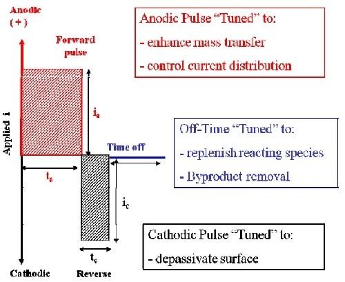 Figure 4 - Generalized pulse/pulse reverse waveform for electropolishing.We have developed and continue to develop surface finishing processes based on pulse/pulse reverse electrolysis utilizing simple, easy-to-control aqueous electrolytes.14 Figure 4 is a generalized pulse/pulse reverse waveform for electropolishing. The anodic pulse is tuned (pulse-time and peak voltage) to enhance mass transport and control current distribution. The cathodic pulse is tuned to depassivate the surface and thereby eliminate the need for hydrofluoric acid or other oxide-removing chemical additions. An off-time may be inserted between the pulses to facilitate replenishment of reacting species and removal of byproducts and heat. While the pulse/pulse reverse waveform contains off-times and cathodic pulses, the material removal rate during pulse/pulse reverse electropolishing is generally higher than or equal to that obtained under direct current (DC) electropolishing. This is because the instantaneous anodic pulse current is much higher than the steady state current obtained under DC conditions and compensates for off-times and cathodic periods such that the average material removal rate (net anodic current density) is equivalent to or greater than DC electropolishing.
Key to the development of the pulse/pulse reverse waveform is the “tuning” of the anodic and cathodic pulses (pulse time and pulse amplitude) as well as the selection of the duration of the off-times. While pulse/pulse reverse waveform parameters cannot be selected a priori, we have developed a series of guiding principles for optimizing the pulse/pulse reverse waveform parameters for a particular application. These guiding principles are summarized below.
By considering the theoretical developments associated with voltage-current responses as a function of time resulting from a single pulse, the concentration profile from the electrode surface to the bulk solution consists of a stationary layer (δs) and an inner “pulsating” layer (δp).15,16,17 As the pulse time is decreased, the thickness of inner pulsating layer becomes smaller, as illustrated in Fig. 5. Assuming linear concentration gradients and conducting a simple mass balance, the inner pulsating layer is proportional to the pulse-time (tp) of the pulse:16
δp = 2[(Dtp)/π]1/2 (3)
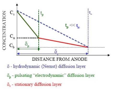 Figure 5 - Linearized hydrodynamic, stationary and pulsating diffusion layers.where D is the diffusion coefficient. More exacting estimates of the thickness of the inner pulsating diffusion layer have been proposed,17 but the key point is the proportionality with pulse-time. Since the inner pulsating layer is proportional to the pulse- time, we refer to the pulsating layer as the “electrodynamic diffusion layer.”18Just as the thickness of hydrodynamic diffusion layer (Nernst diffusion layer) may be adjusted by changing the solution viscosity and/or solution agitation, the electrodynamic diffusion layer may be adjusted by the pulse-time.
In electropolishing, the diffusion layer thickness is relevant in context with the roughness scale of the surface. A microprofile is the case where the diffusion layer thickness is larger than the roughness scale. For electrolysis under microprofile conditions and under mass transport control, the peaks are preferentially removed relative to the recesses and electropolishing is achieved. A macroprofile is the case where the diffusion layer thickness is less than or equal to two times the roughness scale and consequently the diffusion layer follows the surface contour. For electrolysis under macroprofile conditions and under mass transport control, the peaks and recesses are equally removed and the surface roughness generally remains unchanged. That is, electropolishing is not accomplished.
Whether or not the electropolishing process is under mass transport control is determined by the relationship between the pulse- time (tp) and the transition time (τ).17 Although originally developed for electrodeposition, for electropolishing, the transition time may be thought of as the time for the dissolved metal to reach its solubility limit at the electrode surface. The transition time is quantified by the Sand equation and is inversely proportional to the peak current density (ipeak) for single current pulses.
τ = π[(nF)2CD2]/4ipeak2 (4)
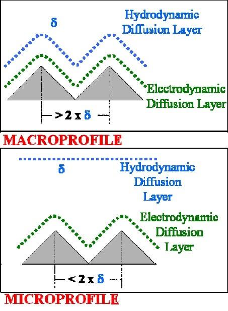 Figure 6 - Representation of hydrodynamic and electrodynamic diffusion layers for a macroprofile and a microprofile.Where n is the number of electrons taking place in the reaction, F is Faraday’s constant and C is the bulk concentration of the reacting species. For cases where the pulse-time is approximately equal to or greater than the transition time, the electrolytic process is under mass transport controlled conditions.19 Conversely, for cases where the pulse-time is substantially less than the transition time, the electrolytic process is not under mass transport control.
We assume that these relationships from single pulse studies are applicable to anodic pulse waveforms with off-times and interspersed anodic/cathodic waveforms with off-times. For electropolishing under macroprofile diffusion layer conditions, the pulsed anodic waveform converts the macroprofile diffusion layer to a smaller electrodynamic macroprofile diffusion layer (Fig. 6). For shorter and shorter anodic pulse-times, the electrodynamic macroprofile diffusion layer will be smaller and smaller (see Eq. 3). At the same material removal rate, the contribution of mass transport will be less for the smaller electrodynamic macroprofile and the material removal will occur preferentially at the peaks. This is due to the fact that the process is less influenced by mass transport and the current distribution is therefore more non-uniform, all else being equal.19Consequently, we have generally found for macroprofile cases, it is desirable to have relatively short anodic pulse-times.
For electropolishing under microprofile diffusion layer conditions, the pulsed anodic waveform converts the microprofile to a smaller microprofile or to a macroprofile (Fig. 6). We have generally found for cases where a microprofile is converted to a smaller microprofile, it is desirable to have relatively high peak current densities in order to have relatively short transition times. In this manner, we maintain mass transport control and the current distribution is more non-uniform and preferentially focused on the peaks. We have generally found for cases where a microprofile is converted to a macroprofile, it is desirable to maintain relatively low peak current densities in order to have relatively long transition times. In this manner, we remove mass transport control and the current distribution is more non-uniform and preferentially focused on the peaks.
In summary, the pulse-time is proportional to the electrodynamic boundary layer thickness and the amplitude of the pulse is inversely proportional to the transition time. For pulse-times substantially less than the transition time, the electrolytic process will not be under mass transport control. For pulse-times approximately equal to or greater than the transition time, the electrolytic process will be under mass transport control. A macroprofile diffusion layer situation is more likely to occur at the beginning of the electropolishing process and a microprofile diffusion layer occurs as the electropolishing process progresses. An understanding of these effects provides the user with a set of guiding principles to optimize the waveform parameters of the electropolishing process for a given application.
The final consideration for developing a pulse/pulse reverse electropolishing waveform is for the case of passive materials. For these materials, anodic only pulses lead to a rougher surface due to the non-uniform breakthrough of the passive film.20,21 In order to depassivate the surface, we intersperse cathodic pulses within the anodic pulses in place of or in conjunction with the offtimes.22,23,24,25 In a general sense, we assume the cathodic pulses remove the oxide film and restore the virgin metal surface as the reverse of reaction (2). The amplitude of the cathodic pulses is selected to remove the passive metal-oxide film and is generally material specific. For metals with stronger oxide films, higher cathodic amplitudes are required. As noted above, some have suggested using non-aqueous or low water content electrolytes to remove the source of oxygen [Eq. (2)], leading to the formation of the passive film. However, from an industrial implementation perspective, these processes are difficult to control, due to the resistivity and hydroscopic nature of the non-aqueous electrolyte.
Results
Low carbon steel automotive planetary gear
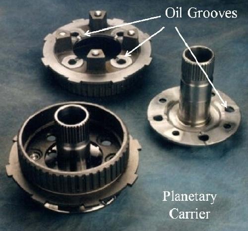 Figure 7 - Planetary carrier and assembly depicting grooves and notches requiring burr removal.Removing rough edges and burrs from manufactured parts is an important industrial challenge. Deburring is often accomplished with manual labor using rudimentary tools and implements. Issues in terms of quality and worker repetitive motion injury (carpel tunnel) are problematic with manual deburring operations. Ford Motor Co. sought a reproducible cost-competitive process to replace their current manual deburring activities.7
The part of interest was a cast iron (SAE 1010 steel) planetary carrier. To increase oil flow to gear teeth, design engineers incorporated a groove into the internal diameter of the cast iron plate and notches across the gear shaft holes. The design engineers quickly realized that burrs would result from the boring/milling processes and sought a cost effective way to remove them (Fig. 7). Initially, Ford engineers began working on an electrochemical deburring process based on an electrolyte consisting of ethylene glycol, ammonium salt, nitric acid and a small amount of water. The ammonium salts were reportedly added to minimize the production of “free” hydrogen. During initial production trials (~8,000 parts), several problems were noticed with the process: (1) limited tool (cathode) lifetime, (2) worker and plant exposure to noxious ammonia odor and (3) high electrolyte cost and maintenance. Specifically, daily additions of nitric acid and water were required to maintain the pH between 5.0 and 6.0, and the electrolyte replacement cost for the automated machine was ~$20,000.
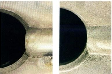 Figure 8 - Groove before and after electrochemical deburring.Based on the guiding principles described above, we developed an electrochemical deburring process using sodium chloride electrolyte and pulsed current electrolysis. Since the flow scheme was envisioned to consist of a macroprofile, we employed short anodic pulses to focus the current field on the burrs. Since 1010 steel is not a strongly passivating material, we did not need to use cathodic reverse pulses. A close-up of the oil slinger groove before and after deburring is shown in Fig. 8. The process was incorporated into an automated machine with 16 stations, eight parts being processed while previously deburred parts (eight) were being unloaded and parts (eight) for deburring were being loaded. The processing time was 45 seconds leading to a through-put of approximately 300 parts per hour. The process operates without the need for active chilling and only requires twice monthly addition of makeup water. The salt water solution is replaced approximately every six months to remove oils and contaminant buildup from drag-in. The cost of electrolyte replacement is a fraction of the cost of the ethylene glycol- based electrolyte. The electrochemical deburring leads to iron hydroxide particles which are removed by a magnetic separator and Ford engineers report excellent tool life and process robustness.7
Stainless steel 300 series fluid control valve
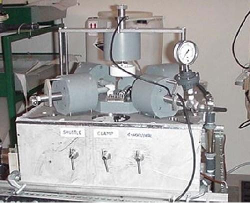 Figure 9 - Machining cell used for electropolishing studies for stainless steel valves.Stainless steel (300 Series) valves, fittings and tubular products are used in the semiconductor industry for process fluid control and delivery. The internal surfaces of these valves must be polished to a mirror-like finish. Previous practice for achieving said finish involved a two-step process: (1) abrasive flow machining (AFM) for bulk material removal of the tool lines, followed by (2) conventional electropolishing to achieve the final mirror-like surface finish. The electropolishing process used a chilled electrolyte solution consisting of a low conductivity and viscous concentrated sulfuric acid/concentrated phosphoric acid as well as some undisclosed proprietary additives. The AFM media was expensive and the combined AFM/electropolishing process was difficult to control.
We developed an electrolytic process for both bulk material removal and electropolishing, based on pulse/pulse reverse waveforms in an aqueous sodium chloride-sodium nitrate electrolyte. We used the same machining cell (Fig. 9) used for the conventional electropolishing process with electrolyte entry/exit through the internal elbow-shaped passages. Due to this flow scheme, we assumed the process was operating under a macroprofile diffusion layer and consequently choose short anodic pulses. Due to the passive nature of the 300 series stainless steel, we also used cathodic pulse interspersed between the anodic pulses to depassivate the surface.23
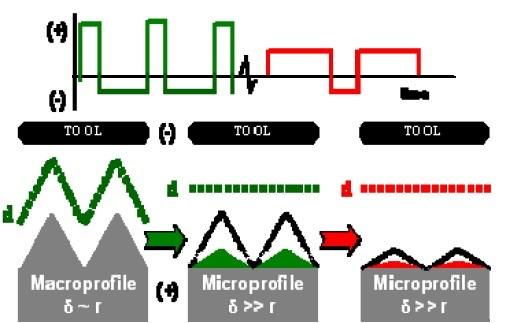 Figure 10 - Waveform sequence used to electropolish stainless steel valves in sodium chloride-sodium nitrate aqueous electrolyte.The beginning Ra [Ra is a common measure of surface roughness based on the arithmetic average of the absolute values of the roughness profile ordinates (peaks and valleys)] was approximately 1 μm and after about 30 sec of pulse/pulse reverse electrolytic processing, the Ra was reduced to approximately 0.2 μm. With continued pulse/pulse reverse processing for times up to 2.0 min, the final Ra remained unchanged at approximately 0.2 μm. The surface was essentially being conformally electroetched for processing times after 30 sec. We concluded that the diffusion layer situation changed initially from a macroprofile to a microprofile. While the short anodic pulses were appropriate for focusing the current field onto the surface asperities for a macroprofile diffusion layer, a long anodic pulse waveform is more appropriate for focusing the current field on the asperities for a microprofile diffusion layer. Consequently, as illustrated in Fig. 10, we used a waveform sequence consisting of short anodic pulses with interspersed cathodic pulses for 30 sec, followed by a waveform with long anodic pulses and interspersed cathodic pulses for an additional 15 sec.25 In this manner we were able to achieve a mirror-like finish with a final Ra of 0.026 μm (Fig. 11).
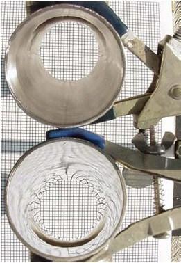 Figure 11 - Stainless steel surface before and after pulse reverse electropolishing in sodium chloride-sodium nitrate electrolyte.In summary, the pulse/pulse reverse electrolytic process was adapted to replace a bulk material removal process and a conventional electropolishing process. The pulse/pulse reverse process used an aqueous low viscosity conductive sodium chloride-sodium nitrate electrolyte which did not require active chilling and was robust and easy to maintain.
Nickel-titanium alloy
Nitinol is an intermetallic of approximately 50% nickel and 50% titanium. Due to its shape memory effect, ductility, corrosion resistance and fatigue strength, nitinol has applications including actuators, dental orthodontics and medical stents. In the case of medical stents, after cutting the stent pattern from a nitinol tube with a laser, the stent is typically electropolished in a chilled solution of concentrated viscous phosphoric acid. This conventional electropolishing process often yields reject rates of 40 to 50%.8
We are developing a pulse/pulse reverse for electropolishing and electrochemical through-mask etching of nitinol materials. Based on preliminary polarization studies, we selected a 30 wt% aqueous sulfuric acid electrolyte.24 The samples used in these preliminary studies were patterned nitinol coupons with lines and spaces of varying dimensions. Due to the feature size of the lines and spaces, we assumed that the process was operating under a microprofile. For electrochemical through-mask etching, these conditions dictated short anodic pulses of relatively high voltage amplitude26 with interspersed cathodic pulse of moderately high amplitude to depassivate the strongly passive surface oxide. Although we have only conducted preliminary experiments with nitinol, the initial results indicate we can obtain a mirror-like finish (Rq ~ 0.1 μm) and good pattern fidelity (Fig. 12). Due to the simple nature of the aqueous electrolyte and the absence of hydrofluoric acid or other fluoride salts to depassivate the surface, we are encouraged that a robust, cost-effective process can be developed for electropolishing nitinol materials with low reject rates.
Niobium
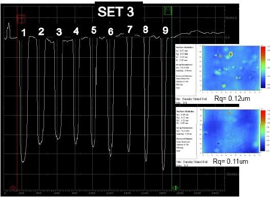 Figure 12 - Electrochemical through-mask etching of patterned nitinol coupons.Niobium is the material of choice for superconducting radio frequency (SRF) cavities used in linear particle accelerators. In order to meet the performance requirements, approximately 125 μm of material must be removed from the internal surface of the SRF cavity. A two-step process is currently used. Buffered chemical polishing is used to remove approximately 100 μm of material resulting in an Ra of approximately 2.0 to 5.0 μm. Electropolishing is then used to remove an additional 25 μm of material to achieve a final surface finish with an Ra of less than 0.2 μm. The electropolishing electrolyte is approximately nine parts sulfuric acid (98%) to one part hydrofluoric acid (48%).2 The process requires special maintenance and handling precautions due to the use of hydrofluoric acid and is difficult to control with approximately 50% of the electropolished SRF cavities exhibiting pits or other surface defects limiting SRF cavity performance.9
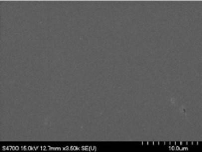 Figure 13 - Surface image of electropolished niobium coupon.We are developing a pulse/pulse/reverse electropolishing process for niobium SRF cavities. In preliminary work, we are developing process parameters using niobium coupons. Our generalized pulse reverse waveform utilizes a short anodic pulse followed by a short cathodic pulse with a relatively long off-time to facilitate heat removal. Our electropolishing electrolyte is aqueous sulfuric acid (~30 wt%) devoid of hydrofluoric acid and other additives. From preliminary coupon studies, we have achieved a mirror-like surface finish free of defects (Fig. 13). Ra values were measured ranging from approximately 0.004 μm to 0.001 μm to 0.0004 μm for scan sizes of 50×50 μm, 10×10 μm, and 2×2 μm, respectively. We are continuing to develop pulse/pulse reverse wavefrom parameters and scaling the process from coupons to single-cell SRF niobium cavities. The aqueous sulfuric acid electrolyte devoid of hydrofluoric acid offers considerable promise for a robust, low cost, safe electropolishing process for SRF niobium cavities.
Conclusions
We have described a pulse/pulse reverse electropolishing process using aqueous electrolytes. We presented guiding principles for pulse/pulse reverse waveform development. These include the proportionality of the pulse-time to the electrodynamic diffusion layer and the inverse relationship of the pulse amplitude to the transition time. Additionally, the relationship of the diffusion layer thickness to the surface asperity characteristic roughness determines a macroprofile or microprofile condition. Finally, for passive materials, cathodic pulses are interspersed to depassivate the surface and off-times may be used to facilitate heat removal. These concepts combined with an understanding of current distribution allow one to develop the appropriate pulse/pulse reverse waveform without undo experimentation. Applications for electrochemical deburring of a low carbon steel automotive part and for electropolishing of stainless steel fluid control valves to an Ra of approximately 0.026 μm were discussed. Additional examples for electropolishing of nitinol (nickel-titanium alloys) and niobium coupons were presented with surface roughnesses ranging from an Ra of approximately 0.12 μm (nitinol) to 0.004-0.0004 μm (niobium). Due to the low viscosity/high conductivity nature of the electrolyte and the absence of hydrofluoric acid our other chemical additives, the pulse/pulse reverse electropolishing is robust, low cost and safe.
Acknowledgment
The authors acknowledge the financial support of Faraday corporate, NIH Grant No.1 R43 HL095216-01A1, DOE P.O. No. 594128, DOE Contract No. DE-SC0004588, Ford Motor Co. and Swagelok Corp. The authors are grateful to Dr. C. Reece and his team at Jefferson Lab for the Atomic Force Microscopy surface roughness measurements of the niobium coupons.
Main image courtesy of Argonne National Laboratory, www.anl.gov.
References
1. D. Landolt, Electrochim. Acta, 32 (1), 1 (1987).
2. H. Tian, et al., J. Electrochem. Soc., 155 (9), D563 (2008).
3. W. Schwartz, “Electropolishing,” Original in Plating, 68 (6), 42 (1981); Update by J. Lindsay, Plating & Surface Finishing, 90 (3), 8 (2003).
4. H. Diepers & O. Schmidt, U.S. Patent 3,689,388 (1972).
5. D. Landolt, P. Chauvy & O. Zinger, Electrochim. Acta, 48 (20-22), 3185 (2003).
6. K. Inoue, U.S. Patent 3,776,827 (1973).
7. K. Stacherski, “Electrochemical Deburring,” Ford PowerTrain Cutting Tool News, 2 (1), (Winter 1996) (available www.FaradayTechnology.com).
8. Private communication of original equipment stent manufacturers to E.J. Taylor (April 21, 2011).
9. L. Cooley, “Perfecting Superconducting Niobium for Teravolt and Megawatt Linear Accelerators,” Iowa State University Colloquium, 11-15-2010; http://www.event.iastate.edu/event/23106/, accessed 07-20-2011.
10. P.A. Jacquet, Trans. Electrochem. Soc., 69, 629 (1936).
11. C. Wagner, J. Electrochem. Soc., 101 (5), 225 (1954).
12. W.C. Elmore, J. Appl. Phys., 10 (10), 724 (1939).
13. H.F. Walton, J. Electrochem. Soc., 97 (7), 219 (1950).
14. E.J. Taylor, J. Appl. Sur. Fin., 3 (4), 178 (2008); Plating & Surface Finishing, 95 (12), 24 (2008).
15. N. Ibl, J.C. Puippe & H. Angerer, Surface Technology, 6(4), 287 (1978).
16. N. Ibl, Surface Technology, 10 (2), 81 (1980).
17. D. Landolt, “Mass Transport in Pulse Plating,” in Theory and Practice of Pulse Plating, J.C. Puippe & F. Leaman (Eds.), NASF, Washington, DC, 1986; pp. 55-71.
18. E.J. Taylor, et al., Plating & Surface Finishing, 89 (5), 88 (2002).
19. O. Dossenbach, “Current Distribution in Pulse Plating,” in Theory and Practice of Pulse Plating, J.C. Puippe & F. Leaman (Eds.), NASF, Washington, DC, 1986; pp. 73-92.
20. C. Zhou, et al., “Electrochemical Machining of Hard Passive Alloys with Pulse Reverse Current,” Trans. NAMRI/SME XXV, 147 (1997).
21. J. Sun, et al., “The Applications of CM-ECM Technology to Metal Surface Finishing,” Trans. NAMRI/SME XXVIII, 245 (2000).
22. J. Sun, E.J. Taylor & R. Srinivasan, J. Materials Processing Technology, 108 (3), 356 (2001).
23. C. Zhou, et al., U.S. Patent 6,402,931 (2002).
24. M. Inman, E.J. Taylor & A. Lozano-Morales, U.S. Patent Application No. 61/353,934, filed Jun. 11, 2010.
25. E.J. Taylor, U.S. Patent 6,558,231 (2003).
26. E.J. Taylor, et al., U.S. Patent Application No. 12/843,968, filed July 27, 2010.
About the Authors
 Dr. E. Jennings Taylor is the Chief Technical Officer and Intellectual Property Director at Faraday Technology, Inc., Clayton, OH. He founded the company to develop and commercialize innovative electrochemical technology using pulse/pulse reverse electric fields. He delivered the William Blum Scientific Achievement award address at SUR/FIN 2008 in Indianapolis, IN. He holds a B.A. in Chemistry from Wittenberg University, an M.A. in technology strategy and policy from Boston University, and M.S. and Ph.D. degrees in materials science from the University of Virginia. He has published more than 125 technical papers and articles and holds 30 patents. He serves as Chairman of the AESF Foundation Research Board.
 Heather A. McCrabb is a Principal Scientist at Faraday Technology, Inc., Clayton, OH. She received her B.S. and M.S. degrees in Chemistry at Wright State University, Dayton, OH, in 1999 and 2001, respectively. Currently, Ms. McCrabb is leading Faraday’s efforts in the development of through-mask electroetching processes for fuel cell applications and the development of electrophoretic deposition processes for coating applications. Her Master’s thesis involved work with the synthesis, characterization, and electrochemical studies of multiple room temperature ionic liquids for application as electrolytes in lithium ion batteries.
 Holly Garich is a Principal Scientist at Faraday Technology, Inc. Mrs. Garich received her B.S. and M.S. degrees in Chemistry at Wright State University, Dayton, OH in 1999 and 2001, respectively. Currently, she is leading Faraday’s efforts in cell and process design for electrodeposition of copper for printed circuit boards, including build-up and testing of reactors for acid copper rinse water and electropolishing of niobium for superconducting radio frequency cavities. Mrs. Garich is a member of the American Chemical Society and NASF.
 Dr. Timothy D. Hall is a Principal Scientist at Faraday Technology, Inc. He received his B.S. degrees from West Virginia University in Chemical Engineering and Mathematics and his doctorate from the University of Notre Dame in Chemical Engineering. Currently, he is working to develop plating and polishing processes for various applications including: hard chromium landing gear coatings, nitinol stent finishing, solid oxide fuel cell chromia diffusion barrier coatings, and through-mask etching for high aspect ratio cavities. Dr. Hall is also a member of the Electrochemical Society.
 Dr. Maria E. Inman is the Research Director at Faraday Technology Inc. She holds a B.E. in Metallurgical and Materials Engineering and a Ph.D. in Materials Engineering from the University of Auckland, New Zealand. Prior to joining Faraday Technology, she completed a two-year term as a post-doctoral research associate at the Center for Electrochemical Science and Engineering at the University of Virginia. While Dr. Inman has recently focused on electrodeposition of chromium coatings from an environmentally-benign trivalent plating bath, electropolishing of passive materials including nitinol, and development of life prediction models for organic coatings, her role on all programs is as an Internal Consultant.
This article was published in 2011 and represents the positions and companies of the authors at that time. There may have been changes in these positions since then.