
Aluminum alloys are extensively used in space programs for both structural and nonstructural applications.
 As is well known, the corrosion resistance of these alloys is quite limited and anticorrosion treatment is needed. Currently, the treatment most often used for improving the corrosion resistance of aluminum alloys is chromate (CrVI-based) conversion coatings (CCC). Due to the high environmental impact of these compounds, the REACH Regulation of the European Union decided to limit/restrict the use of hexavalent chromium. A sunset date of mid-2017 has been already set. For the time being, many chromate-free alternative products are available, but they have been found to be significantly inferior in terms of corrosion protection performances with respect to the chromate options. In this regard, there is a great need to develop high-performance hexavalent chromium-free anticorrosion coatings with low environmental impact and conformity with the EU regulations.
The European Space Agency (ESA) is currently involved in a frame contract with Instituto de Soldadura e Qualidade (ISQ) that is currently ongoing. The objective of this study is to evaluate the anticorrosion behavior of the different alternative pretreatments applied to the most used aluminum alloys. The outcome of this activity will be the identification and the optimization of the most promising anticorrosion pretreatment. Several commercial Cr(VI)-free processes were applied onto aluminum alloys (2024-T3 and 2024-T81) used in the construction of ESA spacecraft in order to investigate their anticorrosive properties compared with Alodine 1200, a widely used conventional CCC. One of these commercial processes presented good anticorrosion performance, even better than Alodine 1200, and these results are presented in this paper.
Salt spray resistance is included in the testing program as well as metallurgical coating evaluations that include microscopy observations before and after testing and electrochemical impedance spectroscopy in order to evaluate surface and microstructural modifications due to degradation mechanisms. Further studies must be performed with this promising alternative, modifying application parameters in order to achieve improved corrosion protection efficiency.
Introduction
Aluminum and its alloys are widely used onboard space vehicles due to a good combination of specific weight versus mechanical properties. These alloys rely on an oxide layer to resist corrosion in many situations through the life of space hardware for spacecraft application. In emergency conditions, prelaunching phase or prolonged storage for reusable spacecrafts, aluminum alloys may be exposed to harsh environments, such as marine atmospheres associated with launch sites or corrosive gases, resulting in loss of passivity and corrosion of the alloy. To protect aluminum alloys against corrosion, it is common to apply a coating system consisting of a coating scheme and a pretreatment on the metal surface of the alloy. Chromium (VI)-based chemical conversion coatings (CCC), in particular Alodine 1200, are so far the most successful pretreatments used on aluminum alloys and still allowed to be applied in the European aeronautic and aerospace industries due to an exemption of compliance to the EU legislation.1
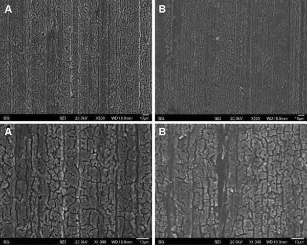 Fig. 1: Illustrative SEM photomicrography obtained in the secondary electrons mode (SE) of the AA2024-T3 surface treated with Alodine 1200 before (a) and after EIS measurements of 7 days of immersion in 0.5 M NaCl (b) (×500 and ×1000)
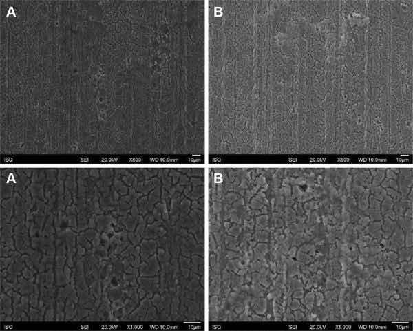 Fig 2: Illustrative SEM photomicrography obtained in the secondary electrons mode (SE) of the AA2024-T81 surface treated with Alodine 1200 before (a) and after EIS measurements of 7 days of immersion in 0.5 M NaCl (b) (×500 and ×1000).
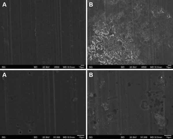 Fig. 3: Illustrative SEM photomicrography obtained in the secondary electrons mode (SE) of the AA2024-T3 surface treated with PreCoat A32 before (a) and after EIS measurements of 7 days of immersion in 0.5 M NaCl (b) (×500 and ×1000)
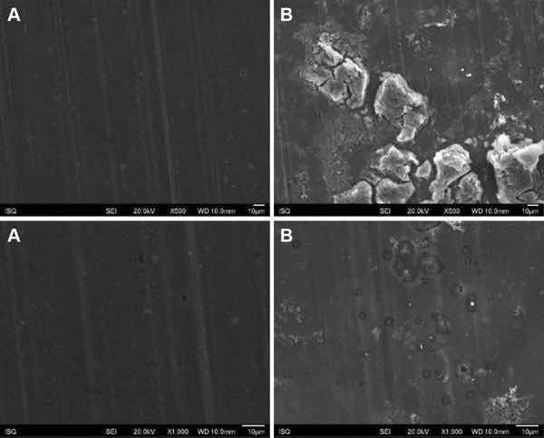 Fig 4: Illustrative SEM photomicrography obtained in the secondary electrons mode (SE) of the AA2024-T81 surface treated with PreCoat A32 before (a) and after EIS measurements of 7 days of immersion in 0.5 M NaCl (b) (×500 and ×1000)
Although working under the umbrella of that exemption, for environmental, health, and safety reasons, ESA is actively working on finding an environmentally and socially friendlier pretreatment. The objective of the present study is to evaluate the suitability and availability of alternative surface treatments to hexavalent chrome which is the standard corrosion protection used on aluminum alloys. The majority of aluminum alloys used for manufacturing spacecraft and ground support structures require corrosion resistance. The selected process applied to widely used alloys shall demonstrate with significant test evidence to meet the performance and reliability requirements necessary for ESA missions. It shall prove to have same (or better) performance with respect to chrome VI treatments which are the current standard. The main objective is the identification and the optimization of the most promising anticorrosion pretreatment.
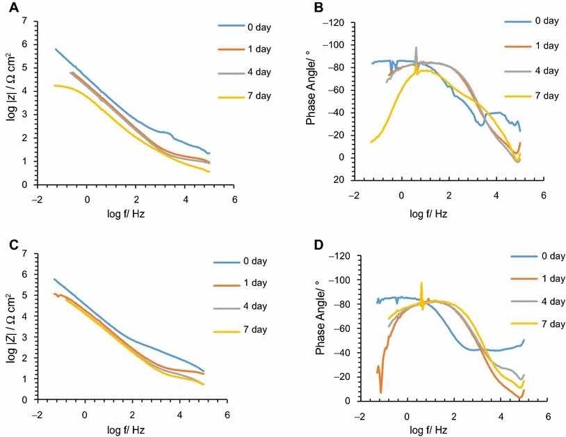 Fig 5: Impedance modulus and phase angle evolution with time for Alodine 1200 coatings: (a) impedance modulus for AA2024-T3 substrates; (b) phase angle for AA2024-T3 substrates; (c) impedance modulus for AA2024-T81 substrates; (d) phase angle for AA2024-T81 substrates
Aluminum alloy 2024-T3 has been extensively used as an aircraft alloy due to its low density and high strength. A major disadvantage of the alloy is its susceptibility to localized corrosion. This is due in part to the copper content (up to 4%), which can establish galvanic cells with the aluminum matrix and produce localized corrosion (especially pitting corrosion and intergranular corrosion).2–4 Aluminum alloy 2024-T3 has a nominal composition of Al, 4.4% Cu, 1.5% Mg, 0.6% Mn, 0.5% Fe, 0.5% Si, 0.25% Zn, 0.10% Cr, 0.15% Ti, and 0.15% other elements. The addition of copper and magnesium as major alloying elements as well as a specific heat treatment makes the AA2024-T3 a highly strengthened alloy for aerospace applications.
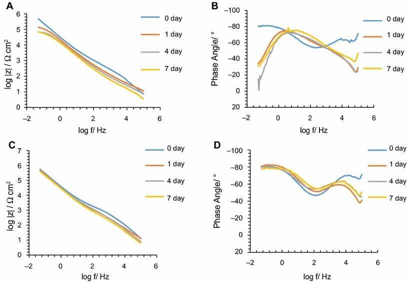 Fig. 6: mpedance modulus and phase angle evolution with time for PreCoat A32 coatings: (a) impedance modulus for AA2024-T3 substrates; (b) phase angle for AA2024-T3 substrates; (c) impedance modulus for AA2024-T81 substrates; (d) phase angle for AA2024-T81 substrates
Aluminum alloy 2024-T81 has the same chemical composition but a different heat treatment (artificial aging). Copper provides both solid solution strengthening and precipitation hardening. The solubility of Cu in aluminum decreases from 5.65 wt% at 548°C to lower than 0.1 wt% at room temperature. The addition of magnesium accelerates and intensifies the precipitation process. Manganese acts as a strengthener and controls grain size. Chromium and titanium are added primarily as grain refiners, while iron and silicon are unwanted impurities in the alloy.5
Chromate conversion coatings (CCC) have been subjected to intensive study over the past decades due to the effective corrosion protection they confer to Al alloys and the desire to develop an effective and environment-friendly replacement.6–8 The composition and structure of CCC formed on pure Al and Al alloys have been investigated extensively using a variety of analytical tools. However, this work deals with commercially available Cr(VI)-free alternatives.
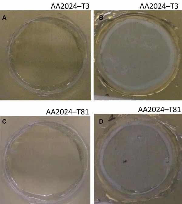 Fig 7: Illustrative photographs of the aluminum substrates treated with Alodine 1200: (a) AA2024-T3 at initial immersion time; (b) AA2024-T3 after 7 days of immersion in 0.5 M NaCl; (c) AA2024-T81 at initial immersion time; (d) AA2024-T81 after 7 days of immersion in 0.5 M NaCl
Alternative commercially available chemical conversion pretreatments for the protection of aluminum alloys were investigated. A prescreening study based on salt spray testing results was carried out using eight commercially available Cr(VI)-free pretreatments, and the corrosion resistance of the alternative pretreatment with better performance was evaluated by electrochemical impedance spectroscopy (EIS). The results showed that one pretreatment (PreCoat A32) provides good corrosion protection both on AA2024-T3 and AA2024-T81 substrates.
This paper presents some results obtained with the study carried out, comparing the anticorrosion performance of PreCoat A32 with the one conferred by Alodine 1200, both applied onto 2024-T3 and 2024-T81 aluminum alloys.
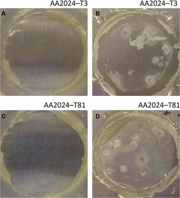 Fig 8: Illustrative photographs of the aluminum substrates treated with PreCoat A32: (a) AA2024-T3 at initial immersion time; (b) AA2024-T3 after 7 days of immersion in 0.5 M NaCl; (c) AA2024-T81 at initial immersion time; (d) AA2024-T81 after 7 days of immersion in 0.5 M NaCl
Experimental
Preparation of the metallic substrates
All the aluminum substrate panels (AA2024-T3 and AA2024-T81) were submitted to the following sequence: cleaning, water rinsing, deoxidizing, water rinsing, application of the conversion coating pretreatment solution (according to specifications and application parameters), and drying.
Pretreatments
Alodine 1200-tested specimen surface presented an iridescent golden color for all the alloys, and PreCoat A32-coated panels kept the initial metallic aspect and appeared colorless. This pretreatment is a hexavalent chrome-free water-based conversion coating for different aluminum alloys based on zirconium (IV), chromium (III), and fluorides. It forms a transparent to slightly visible layer that improves the corrosion protection of bare aluminum alloys. It can be used in spray and immersion (dip) applications as is proposed by vendor.
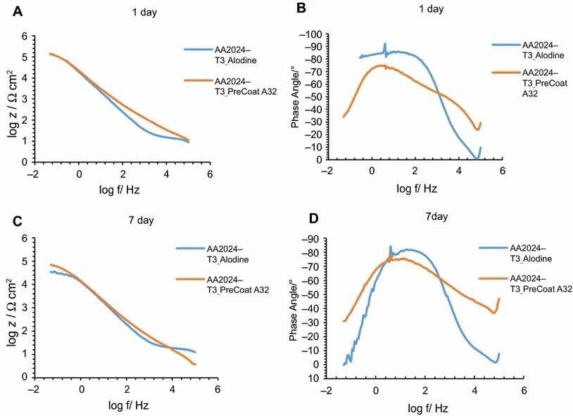 Fig 9: Impedance modulus and phase angle evolution with time for AA2024-T3 substrates: (a) impedance modulus at 1-day immersion time; (b) phase angle at 1-day immersion time; (c) impedance modulus at 7-day immersion time; (d) phase angle at 7-day immersion time
Coating morphology and composition characterization
The morphology of the coatings was examined by scanning electron microscopy (SEM), using a field emission JEOL JSM-6500F.
Impedance measurements
The EIS measurements were taken using a VoltaLab PGZ100, and all the measurements were taken at room temperature in a Faraday cage. A three-electrode arrangement was used. A silver/silver chloride electrode (Ag/AgCl) was used as reference, and a platinum wire was used as the counter electrode. The cell was formed by attaching a perspex cylinder to the specimen surface, providing an exposed area of 6.2 cm2 for the working electrode. The electrolytic solution consisted of a 0.5 M NaCl solution. Prior to EIS analysis, the open-circuit potential of the specimen was continuously monitored from the commencement of immersion in the electrolyte for 50 min. The EIS data were acquired over the frequency region from 100 kHz to 50 Hz at 20 frequencies per decade, with an AC voltage amplitude of 10 mV. At least two measurements were taken for each condition.
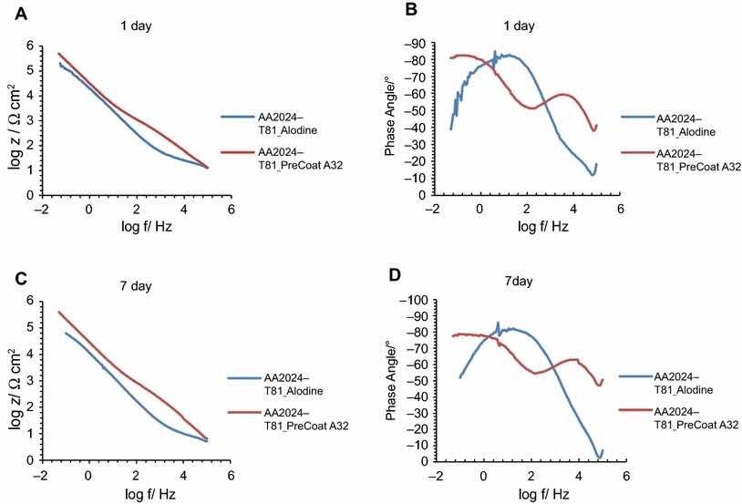 Fig 10: Impedance modulus and phase angle evolution with time for AA2024-T81 substrates: (a) impedance modulus at 1-day immersion time; (b) phase angle at 1-day immersion time; (c) impedance modulus at 7-day immersion time; (d) phase angle at 7-day immersion time
Salt spray testing
Neutral salt spray testing was carried out according to ASTM B117 with a 5% NaCl solution at 35°C. The aluminum panels were placed in the cabinet between 15° and 30° from the vertical for 168 h (7 days). The panels were not allowed to contact other surfaces in the chamber or the condensate nor with each other. After exposure, test panels were rinsed in deionized water to remove salt deposits from their surface and then immediately dried. Test panels were inspected, where the number of spots or pits were counted and recorded. Areas within 5 mm from the edges of the panel, identification markings, and holding points were excluded from inspection. Differences in color between the test panels and the control panels were not cause for rejection. The salt spray exposure was carried out in a salt spray chamber Q-FOG, model CCT1100.
The progress of corrosion was evaluated visually and from macrographs recorded of the exposed surfaces.
Results and Discussion
Coating morphology
Figures 1, 2, 3, and 4 show SEM images of the morphology of the resulting coatings. Alodine 1200 coatings formed on the two substrates present a different morphology than PreCoat A32 coatings formed on the same substrates. Alodine 1200 coatings present a typical cracked pattern, and PreCoat A32 coatings present a smoother pattern before immersion in 0.5 M NaCl solution. Some pores are visible on the surface of PreCoat A32 that are most likely pores in the coating. The generally cracked surface morphology is typical of Cr(VI)-based coatings. It has been described by various authors9–11 and is likely the result of shrinkage stresses generated during drying out of the coatings. Cracks in the coatings have been suggested to be beneficial9 for paint adhesion as they allow for mechanical interlocking between the chromate coatings and subsequently applied organic finishes.
Both pretreatments present few localized corrosion points after 7 days of immersion in 0.5 M NaCl solution. No significant differences in the coatings morphology were found for AA2024-T3 and AA2024-T81 for the same pretreatment.
Impedance measurements
The corrosion behavior of the pretreated substrates was investigated by EIS. Figures 5 and 6 depict the EIS plots for the two pretreatments applied on the two alloys after 0, 1, 4, and 7 days of immersion in 0.5 M NaCl solution. The EIS data are presented in the form of Bode plots, i.e., the impedance modulus plot and the phase angle plot. In the EIS Bode plots, the impedance at lowest frequencies can be correlated with the corrosion resistance of the system. Thus, higher impedance values account for enhanced corrosion protection. The impedance spectra show that PreCoat A32 pretreatment applied onto both aluminum alloys provides higher impedance values compared to Alodine 1200 pretreatment applied onto the same substrates. This effect can be the result of a decrease in the corrosion rate of the substrate in the presence of PreCoat A32 films and/or an enhanced barrier effect that increases the protection of the natural oxide film. Figures 7 and 8 shows the appearance of surfaces treated with the two pre-treatments before and after 7 days of immersion in 0.5 NaCl. Both alloys present small pits after 7 days of immersion.
Figures 9 and 10 compare EIS plots for the two pretreatments at 1 and 7 days of immersion in 0.5 M NaCl solution applied onto AA2014-T3 and AA2024-T81, respectively.
In all the cases, except for PreCoat A32 pretreatment onto AA2024-T81, a broad time constant can be observed, suggesting overlapping two time constants that can be associated with the presence of the anodic porous aluminum oxide film and the protective layers, respectively.12 Further, the alloys treated with PreCoat A32 pretreatment showed impedance modulus slightly higher than the alloys treated with Alodine 1200 for longer immersion times. PreCoat A32 pretreatment onto AA2024-T81 shows a separation of the two time constants. The time constant at higher frequencies is associated with the protective layer, and the time constant evident at the lower frequencies is associated with the porous anodic aluminum layer.
More precise analysis is possible from estimation of the coating capacitance and coating resistance; the established approximation methods were used.13 The equation C = −1/2πfZimag was used for the capacitance estimation, where f is the frequency of a maximum in the phase angle value and Zimag is the imaginary part of the impedance at this frequency. The data used in this case correspond to the time constants present in the higher frequency region, associated with the outer thin coating layer. The equation R = Zreal was used for the resistance estimation, where Zreal is the real part of the impedance at the frequency with minimum phase angle. In this case, the data used for the resistance estimation correspond to the minimum phase angles present at low frequencies. The estimated values are presented in Table 1.
Table 1 Estimated parameters from EIS after immersion in 0.5 M NaCl solution
| Days: 0 | Days: 1 | Days: 4 | Days: 7 | |
| AA2024-T3 | ||||
| Alodine 1200 | ||||
| • Rs (Ω cm2) | 23.0 | 9.4 | 8.4 | 3.6 |
| • Rct (Ω cm2) | 1.32 × 10⁵ | 6.3 × 10⁴ | 5.1 × 10⁴ | 1.3 × 10⁴ |
| • Cdl (µF cm−2) | 8.89 | 3.90 | 4.92 | 11.81 |
| AA2024-T81 | ||||
| Alodine 1200 | ||||
| • Rs (Ω cm2) | 22.9 | 16.8 | 5.4 | 5.4 |
| • Rct (Ω cm2) | 2.0 × 10⁵ | 7.6 × 10⁴ | 6.3 × 10⁴ | 6.0 × 10⁴ |
| • Cdl (µF cm−2) | 5.78 | 6.61 | 24.68 | 6.48 |
| AA2024-T3 | ||||
| PreCoat A32 | ||||
| • Rs (Ω cm2) | 7.6 | 11.3 | 7.4 | 3.7 |
| • Rct (Ω cm2) | 4.8 × 10⁵ | 1.3 × 10⁵ | 6.9 × 10⁴ | 6.9 × 10⁴ |
| • Cdl (µF cm−2) | 0.37 | 1.09 | 1.99 | 4.14 |
| AA2024-T81 | ||||
| PreCoat A32 | ||||
| • Rs (Ω cm2) | 12.8 | 13.3 | 8.1 | 6.6 |
| • Rct (Ω cm2) | 5.6 × 10⁵ | 5.0 × 10⁵ | 4.5 × 10⁵ | 3.9 × 10⁵ |
| • Cdl (µF cm−2) | 0.02 | 0.07 | 0.02 | 0.02 |
The results obtained confirm the qualitative analysis previously made. Specimens treated with PreCoat A32 present lower values for the double-layer capacitance. This is evidence of the better protection high frequency behavior and indicates that the double-layer process is more difficult to establish at the surface; therefore, the corrosion process occurs with more difficulty.14
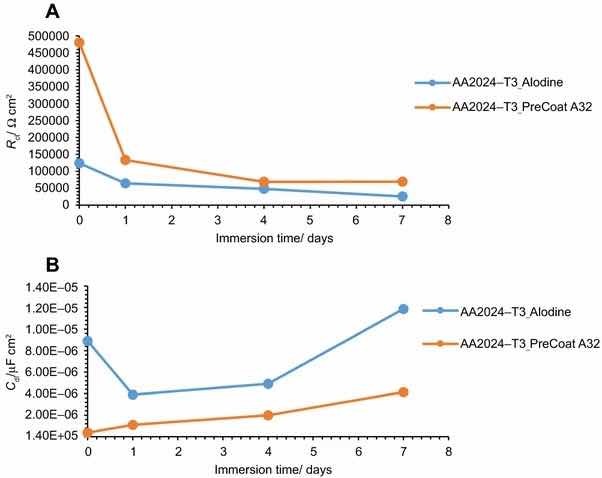 Fig 11: Evolution of coating (a) resistance and (b) capacitance with immersion time onto AA2014-T3.
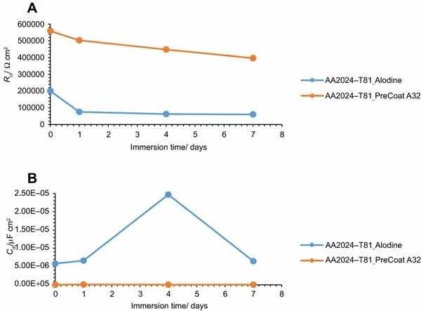 Fig 12: Evolution of coating (a) resistance and (b) capacitance with immersion time onto AA2014-T81.
The specimens treated with Alodine 1200 present lower values for the lower frequency resistance parameter. Higher values for this parameter (around 5 × 10⁵ W cm2) can be determined for samples treated with PreCoat A32, which indicate that charge transfer occurs with more difficulty.
The variation of the resistance and capacitance of the two pretreatments with immersion time is shown in Figs. 11 and 12. Some changes occur during exposure to the NaCl solution as evidenced by the phase angle plots. The resistance reveals a decrease from the commencement of immersion (more evident for the PreCoat A32 onto AA2014-T3) maintaining values of the same order of magnitude until the end of immersion time for each one of the coatings. However, values for PreCoat A32 are significantly higher than those observed for Alodine 1200, particularly for the AA2014-T81 substrates. The capacitance of the pretreatment films slightly increases with time, although remaining in the same order of magnitude for the pretreated substrates. This is more evident for the PreCoat A32 films. Simultaneously, the film resistance decreases by one order of magnitude for all the pretreatments under study. These changes are associated with water penetration in the pretreatment film structure.15
The obtained values for resistance of all the specimens show that we are dealing with films which have a good corrosion protection effect. From all these specimens, the samples treated with PreCoat A32 pretreatment are the ones that present better protection results since they showed the highest resistance values. Both the higher coating resistance and the lower capacitance values are evidence of the improved barrier properties of the PreCoat A32 coatings. This behavior is not presently well understood and will be examined in more detail in future work.
Table 2: Pit count after 168h of salt spray resistance test on Alodine 1200 surface-treated samples
| Substrate | Panel Reference | Pit Count after 168h NSS |
| AA2024-T3 | 1A1 | 3 |
| AA2024-T3 | 1A2 | 0 |
| AA2024-T3 | 1A3 | 2 |
| AA2024-T3 | 1A4 | 1 |
| AA2024-T3 | 1A4 | 1 |
| AA2024-T81 | 2A1 | 7 |
| AA2024-T81 | 2A2 | 6 |
| AA2024-T81 | 2A3 | 5 |
| AA2024-T81 | 2A4 | 6 |
| AA2024-T81 | 2A5 | 6 |
No corrision; Few corrosion
Table 3: Pit count after 168h of salt spray resistance test on PreCoat A32 surface-treated samples
| Substrate | Panel Reference | Pit Count after 168h NSS |
| AA2024-T3 | 1B1 | 5 |
| AA2024-T3 | 1B2 | 3 |
| AA2024-T3 | 1B3 | 3 |
| AA2024-T3 | 1B4 | 3 |
| AA2024-T3 | 1B4 | 2 |
| AA2024-T81 | 2B1 | 5+ |
| AA2024-T81 | 2B2 | 5+ |
| AA2024-T81 | 2B3 | 3 |
| AA2024-T81 | 2B4 | 3 |
| AA2024-T81 | 2B5 | 3 |
No corrision; Few corrosion
Table 4: Summarized results obtained after 168h of salt spray test
| Aluminum alloy | Alodine 1200 | PreCoat A32 |
| AA2024-T3 | No/little evidence of corrosion | Few density corrosion spots/pits |
| AA2024-T81 | No/little evidence of corrosion | Few-medium density corrosion spots/pits |
Corrosion resistance according to MIL-DTL-81706 requirements: (a) No more than 5 isolated spots or pits, none larger than 787 µm (0.031 in) diameter, per test specimen. (b) No more than 15 isolated spots or pits, none larger than 787 µm (0.031 in) in diameter, on the combined surface area of five test specimens, subjected to salt spray test
Salt spray testing
Tables 2 and 3 show the pit count after salt spray resistance tests on surface pretreated samples.
A summary of the inspection results performed on the surface area of the five test specimens of each aluminum alloy/pretreatment under study after 168 h of salt spray testing is presented in Table 4. The evaluation criteria were performed according to MIL-DTL-5541 and MIL-DTL-81706.16,17
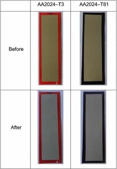 Fig 13: Illustrative photographs of the test panels pretreated with Alodine 1200, before and after salt spray tests.
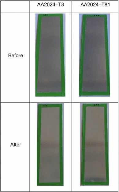 Fig 14: Illustrative photographs of the test panels pretreated with PreCoat A32, before and after salt spray tests. Figures 13 and 14 illustrate the coated test panel surfaces after the exposure to salt spray tests.
Table 2 and Fig. 13 show the results for Alodine 1200 onto the aluminum substrates. This conversion coating passed the minimum 168-h requirements for aluminum alloys except for 2024-T81, in which more than 15 isolated spots or pits on the combined surface area of five test specimens. This temper corresponds to an artificial aging that results in a more corrosion susceptible microstructure.
Table 3 and Fig. 14 show the results for PreCoat A32 onto the aluminum substrates. This pretreatment passed the minimum 168-h requirements for all the alloys. The few spots/pits are present on the top and bottom of the test panels.
The influence of the thermal treatment on the AA2024 was analyzed, and it was noticed that in general more corrosion signs are visible for the T81 treatment than for the T3. This is an expected result once T81 temper condition corresponds to an artificial aging and the effect of artificial aging on the pitting corrosion was studied,4 and it was found that artificial aging had a strong effect on polarization curves and localized corrosion morphology of AA2024.
Conclusions
A commercial Cr(VI)-free process was applied onto aluminum alloys (2024-T3 and 2024-T81) used in the construction of ESA spacecraft, in order to investigate their anticorrosive properties compared with Alodine 1200. The difference between the two aluminum alloys is the different heat treatment (artificial aging for AA2024-T81).
The morphology of the resulting coatings is different which can result in the different compositions. Alodine 1200 coatings formed on the two substrates present a typical cracked pattern, and PreCoat A32 pretreatment presents a smoother pattern before immersion in 0.5 M NaCl solution.
Both EIS analysis and SST results revealed that PreCoat A32 coatings provide improved corrosion protection to both the AA2024 aluminum alloys. This means that this commercially available pretreatment is a promising alternative for chromium (VI)-based chemical conversion coatings (CCC) that are still allowed to be applied in the European aeronautic and aerospace industries. The improved protection provided by this pretreatment will be further studied by the authors.
This paper was presented (poster presentation) at the 12th Coatings Science International Conference (COSI) on June 26– 30, 2016 in Noordwijk, the Netherlands.
Acknowledgments: The presentation of these results has received funding from the Portuguese Foundation for Science and Technology in the scope of the project UID/EMS/00712/2013.
References
- Official Journal of the EU L 37/19 from 13.02.2003
- Jo, B, Merten, E, Battochi, D, Bierwagen, GP, “Aluminium Alloy 2024-T3 Protection by Magnesium-Rich Primer with Chromate-Free Metal Salts.” Prog. Org. Coat., 78 446 (2015)
- Santa Coloma, P, Izagirre, U, Belaustegi, Y, Jorcin, JB, Cano, FJ, Lapeña, N, “Chromium-Free Conversion Coatings Based on Inorganic Salts (Zr/Ti/Mn/Mo) for Aluminum Alloys Used in Aircraft Applications.” Appl. Surf. Sci., 345 24 (2015)
- Capelossi, VR, Poelman, M, Recloux, I, Hernandez, RPB, de Melo, HG, Olivier, MG, “Corrosion Protection of Clad 2024 Aluminum Alloy Anodized in Tartaric-Sulfuric Acid Bath and Protected with Hybrid Sol–Gel Coating.” Electrochim. Acta, 124 69 (2014)
- Williams, M, “An Alternative to Chromates for Corrosion Protection for Aluminium Alloys,” Master’s Thesis, Master of Science (2011)
- Xia, Lin, McCreery, Richard L, “Chemistry of a Chromate Conversion Coating on Aluminum Alloy AA2024-T3 Probed by Vibrational Spectroscopy.” J. Electrochem. Soc., 145 (9) 3083–3089 (1998)
- Hughes, AE, Taylor, RJ, Hinton, BRW, “Chromate Conversion Coatings on 2024 Al Alloy.” Surf. Interf. Anal., 25 223–234 (1997)
- Chidambaram, Devicharan, Clayton, Clive R, Kendig, Martin W, Haladaa, Gary P, “Surface Pretreatments of Aluminum Alloy AA2024-T3 and Formation of Chromate Conversion Coatings II. Composition and Electrochemical Behavior of the Chromate Conversion Coating.” J. Electrochem. Soc., 151 (11) B613–B620 (2004)
- Oki Microstructural and Compositional Characterisation of Chromate Pretreatment on Aluminium. ISRN Materials Science 2013 (2013).
- Osborne, JH, “Observations on Chromate Conversion Coatings from a Sol-Gel Perspective.” Prog. Org. Coat., 41 (4) 280–286 (2001)
- Oki, M, Charles, E, “Chromate Conversion Coating on Al-0.2 wt% Fe Alloy.” Mater. Lett., 63 (23) 1990–1991 (2009)
- Zubillaga, O, Cano, FJ, Azkarate, I, Molchan, IS, Thompson, GE, Cabral, AM, Morais, PJ, “Corrosion Performance of Anodic Films Containing Polyaniline and TiO2 Nanoparticles on AA3105 Aluminium Alloy.” Surf. Coat. Technol., 202 5936–5942 (2008)
- Cottis, RC, Turgoose, S, Electrochemical Impedance and Noise. NACE International, USA (1999)
- Balaskas, AC, et al., Prog. Org. Coat., 71 181–187 (2011)
- Cabral, AM, et al., Prog. Org. Coat., 54 322–331 (2005)
- MIL-DTL-5541F, “Detail Specification: Chemical Conversion Coatings on Aluminium and Aluminium Alloys” (11 JUL 2006)
- MIL-C-81706, “MILITARY Specification: Chemical Conversion Materials for Coating Aluminium and Aluminium Alloys” (30 JUN 1970)
Author information: André Carreira, André Pereira, Elisabete Vaz, Ana Maria Cabral, Tommas Ghidini, Lucia Pigliaru, and Thomas Rohr.
Authors and Affiliations: A. F. Carreira, A. M. Pereira, E. P. Vaz, and A. M. Cabral are with ISQ – Instituto de Soldadura e Qualidade, Oeiras, Portugal. T. Ghidini, L. Pigliaru, and T. Rohr are with ESTEC-ESA, Noordwijk, The Netherlands
Open Access This article is distributed under the terms of the Creative Commons Attribution 4.0 International License (http://creativecommons.org/licenses/by/4.0/), which permits unrestricted use, distribution, and reproduction in any medium, provided you give appropriate credit to the original author(s) and the source, provide a link to the Creative Commons license, and indicate if changes were made.